July 19, 2024 By Muhammad Ali 5 minutes read

Spur gears are most commonly used gears in industry. You’ll find them in clocks, washing machines, electric screwdrivers, and even in industrial machinery. Their efficiency and simplicity make them ideal for applications where noise and vibration are not major concerns.
Because of their straight teeth, spur gears engage smoothly and create minimal friction, which means less wear and tear over time. They are the most common type of gears, featuring straight teeth cut parallel to the gear’s axis.
In this article, we will learn in detail about the critical terminology related to spur gears. We’ll also learn into the essential formulas needed for gear calculations. By the end of this guide, you’ll have a solid grasp of spur gear mechanics, making your designs more efficient and reliable.


1. Gear Ratio Calculation
Gear Ratio = (No. of Teeth on Driven Gear) / (No. of Teeth on Driving Gear)
2. Diametral Pitch Calculation
Diametral Pitch (P) = Number of Teeth (N) / Pitch Diameter (D)
3. Pitch Diameter Calculation
Pitch Diameter (D) = Number of Teeth (N) / Diametral Pitch (P)
4. Circular Pitch Calculation
Circular Pitch (p) = (π × Pitch Diameter (D)) / Number of Teeth (N)
5. Module Calculation
Module (m) = Pitch Diameter (D) / Number of Teeth (N)
6. Addendum Calculation
Addendum (a) = 1 / Diametral Pitch (P)
7. Dedendum Calculation
Dedendum (d) = 1.25 / Diametral Pitch (P)
8. Tooth Thickness Calculation
Tooth Thickness = π / (2 × Diametral Pitch (P))
9. Base Circle Diameter Calculation
Base Circle Diameter (Db) = Pitch Diameter (D) × cos(Pressure Angle)
10. Contact Ratio Calculation
Contact Ratio = Arc of Action / Circular Pitch
Designing spur gears requires careful attention to several key factors to ensure efficiency and reliability.
Material Selection: Choose materials based on load capacity, wear resistance, noise reduction, and cost. Common options include steel, cast iron, bronze, and plastics.
Gear Tooth Profile: The involute profile ensures smooth operation. Tip relief and undercutting can prevent interference and reduce noise.
Load and Stress Analysis: Analyze static and dynamic loads. Use bending stress (Lewis formula) and contact stress (Hertzian theory) calculations. Incorporate safety factors to account for unexpected loads.
Gear Ratios and Speed: Calculate gear ratios to match application needs. Higher ratios increase torque but reduce speed.
Manufacturing Tolerances: Maintain precise tolerances for tooth thickness, pitch diameter, and runout. Implement strict quality control to ensure gears meet specifications.
Noise and Vibration Control: Use profile modifications, softer materials, and damping methods to minimize noise and vibration.
Backlash and Clearance: Adjust backlash to prevent binding and ensure smooth operation. Provide adequate clearance for lubrication and thermal expansion.
Understanding spur gears is essential for both engineering students and professionals. This guide has covered crucial terminology, key calculation formulas, and important design considerations.
By mastering terms like addendum, dedendum, pitch diameter, and module, and applying formulas for gear ratio, circular pitch, and tooth thickness, you can design gears that mesh correctly and operate efficiently. Practical considerations like material selection, load analysis, lubrication, and noise control ensure the reliability and longevity of gear systems. Real-world examples and step-by-step calculations illustrate the application of these principles.
With this knowledge, you are well-equipped to tackle gear design challenges, ensuring your gears perform optimally in various applications. Keep experimenting and applying these concepts to become proficient in gear engineering.
If you have any questions or need further resources, feel free to explore additional materials or seek professional guidance.
A spur gear is a type of gear with straight teeth mounted on a parallel shaft, used to transmit motion and power efficiently between two rotating shafts.
Spur gears work by meshing their teeth with those of another gear, transmitting torque and rotational motion from one gear to the other.
Spur gears are used in clocks, washing machines, conveyors, industrial machinery, and automotive transmissions.
Spur gears have straight teeth; helical gears have angled teeth and offer smoother, quieter operation.
The gear ratio is calculated by dividing the number of teeth on the driven gear by the number of teeth on the driving gear.
Spur gears can be made from steel, cast iron, bronze, and plastics, depending on the application requirements.
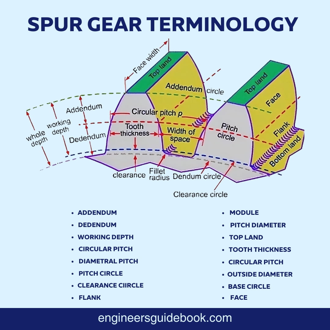
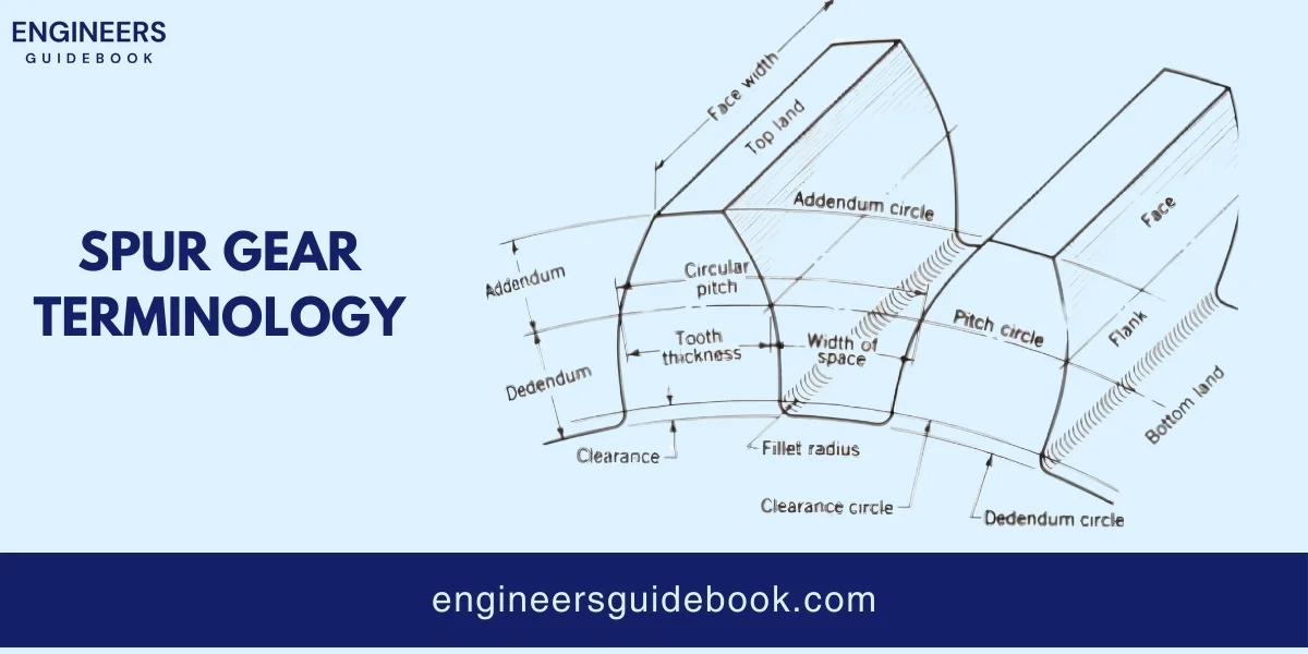
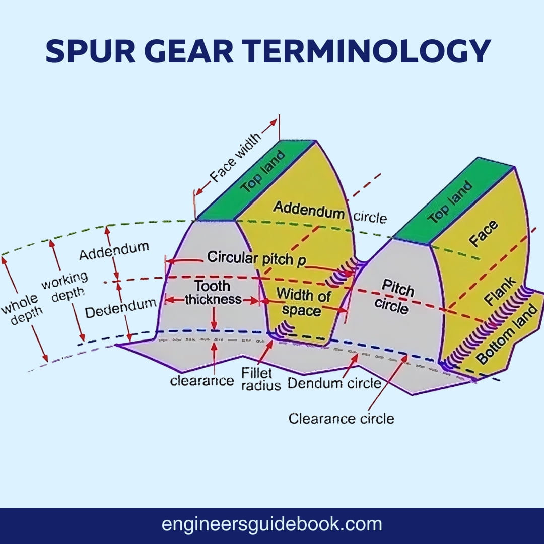
The pitch diameter is the diameter of the pitch circle, which is an imaginary circle that rolls without slipping with another gear’s pitch circle.
The module is the ratio of the pitch diameter to the number of teeth, indicating the size of the gear teeth.
Advantages include simplicity in design, ease of manufacture, high efficiency, and the ability to transmit large amounts of power.
Backlash is the slight clearance or play between mating gear teeth, preventing gears from jamming and allowing for thermal expansion and lubrication.
Addendum is the radial distance from the pitch circle to the top of the tooth.
Dedendum is the radial distance from the pitch circle to the bottom of the tooth.
Circular pitch is calculated as the circumference of the pitch circle divided by the number of teeth.
The fillet radius is the rounded corner at the base of the tooth, reducing stress concentrations and increasing gear strength.
Lubrication reduces friction, wear, and overheating, ensuring smooth and efficient gear operation.

Muhammad Ali holds a PhD in Mechanical Engineering from MIT and is a writing specialist. His groundbreaking research on sustainable energy systems and renewable energy integration has earned him numerous accolades. His passion for innovation and education shines through in his insightful and inspiring writings.
Explore the Engineer’s Guidebook! Find the latest engineering tips, industry insights, and creative projects. Get inspired and fuel your passion for engineering.
© 2023-2024 Engineer’s Guidebook. All rights reserved. Explore, Innovate, Engineer.
3 Responses
your writing seems like you are professional and have knowledge about the this topic. and your blog is neat and good looking.
i enjoy it!
I just Embark into the breathtaking universe of engineering. Read this article this is good one.
The article provides an excellent, clear, and comprehensive guide on spur gear terminology and calculations. It’s a great resource!