Search

Centrifugal Pumps | Working, Formulas & Applications |

Centrifugal Pumps | Working, Formulas & Applications |

June 27, 2024       By Muhammad Ali     9 minutes read

Centrifugal pumps (engineers guidebook )

Table of Contents

Facebook
Twitter
LinkedIn
WhatsApp

1. Introduction

Centrifugal pumps are one of the most widely used types of pumps in industry today. They are found in applications ranging from water supply and wastewater treatment to chemical processing and power generation.

Centrifugal pumps are mechanical devices designed to move fluids by converting rotational energy into fluid energy. This rotational energy typically comes from an engine or electric motor. The primary function of a centrifugal pump is to transfer fluid from one place to another by using a rotating impeller.

In this article, we’ll dive deeper into how centrifugal pumps work, their key components, common applications, and important considerations for selecting and operating them.

Definition:

Centrifugal pumps are mechanical devices used to transport fluids by converting mechanical energy from an external source, such as an electric motor, into kinetic energy in the fluid being pumped.
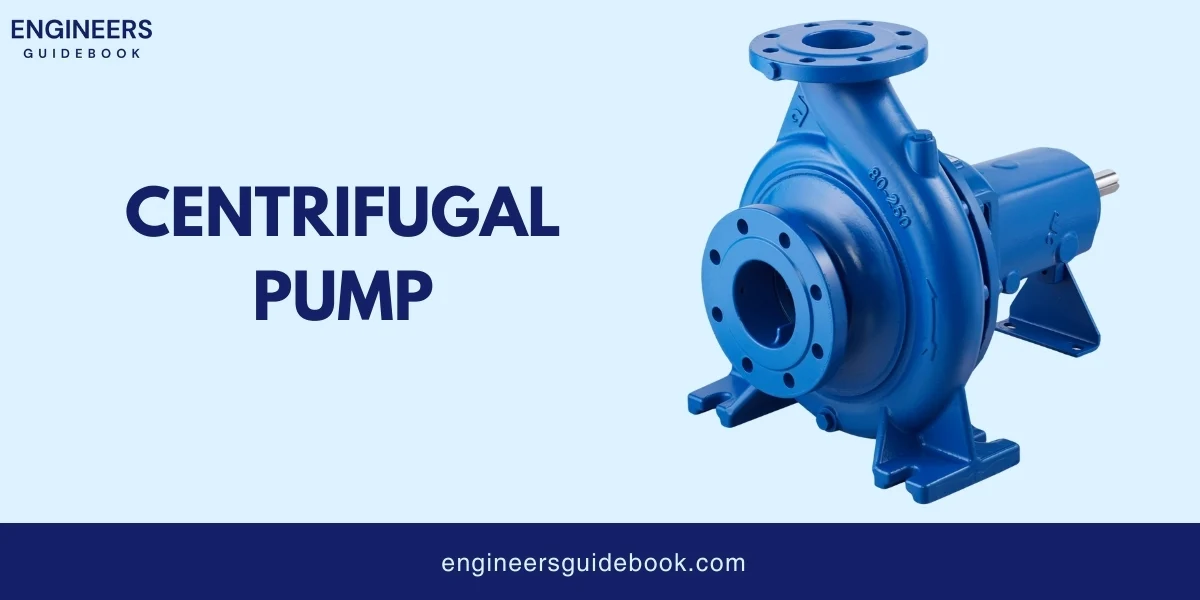
Centrifugal pump

2. Historical Background

Centrifugal pumps have an interesting history:
  • 1600s: Scientists started to understand how spinning motions could move liquids.
  • 1698: Thomas Savery made a pump that used steam power. It wasn’t exactly like today’s pumps, but it was a big step forward.
  • 1730s: A man named Denis Papin created the first true centrifugal pump.
  • 1800s: As machines got better, so did pumps. They started to look more like the ones we use today.
  • 1900s to now: Engineers kept making pumps work better. They made them from stronger materials and designed them to use less energy.

3. Components of Centrifugal Pumps

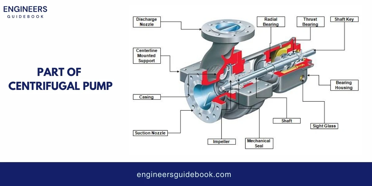
Some main components of centrifugal pump.

  1. Impeller
  2. Casing
  3. Shaft
  4. Bearings
  5. Seals
  6. Wear rings
  7. Coupling
  8. Base plate and frame


Part of centrifugal pump

3.1. Impeller

The impeller is the heart of a centrifugal pump. It spins to move the liquid. Impellers are of three types.
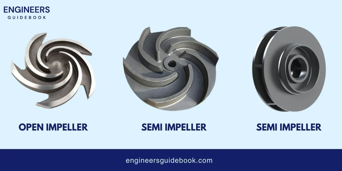
  • Open Impeller: Consists of vanes attached to a central hub without sidewalls. Suitable for handling fluids with solids or high viscosity. Easy to clean and maintain.
  • Semi-open Impeller: Features vanes with a single sidewall. Offers a balance between strength and ease of cleaning, suitable for moderate solids and slurries.
  • Closed Impeller: Enclosed by two sidewalls, creating a strong and efficient design for handling clean fluids. It provides higher efficiency but is more prone to clogging.


Types of impellers

3.2. Casing

The casing is the outer part of the pump that holds everything together.
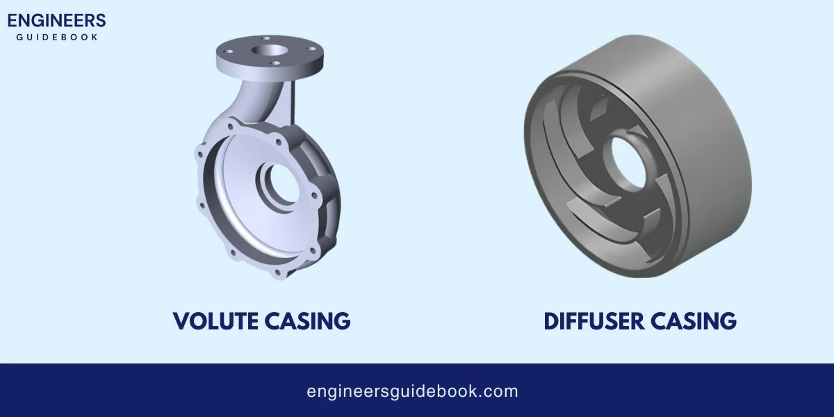
  • Volute Casing: Spiral-shaped casing that reduces fluid velocity and converts kinetic energy into pressure. Commonly used in single-stage pumps.
  • Diffuser Casing: Contains a series of stationary vanes that surround the impeller, providing gradual deceleration and pressure increase. Used in multi-stage pumps for higher efficiency.


Types of casing

3.3. Shaft

The shaft is a rod that holds the impeller and makes it spin.
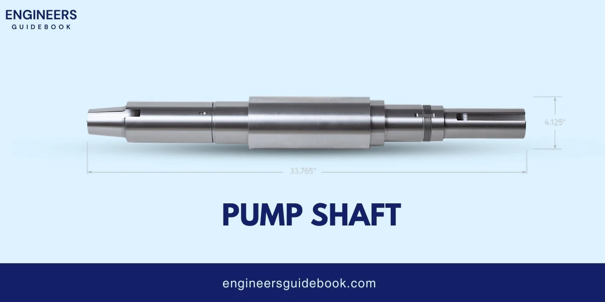
  • Material: Typically made from stainless steel, carbon steel, or alloy steel for strength and corrosion resistance.
  • Design Considerations: Must withstand torque and bending forces, maintain alignment, and minimize vibration. Shaft diameter and length are critical for the performance of centrifugal pumps.


Pump shaft

3.4. Bearings

Bearings help the shaft spin easily without wearing out.
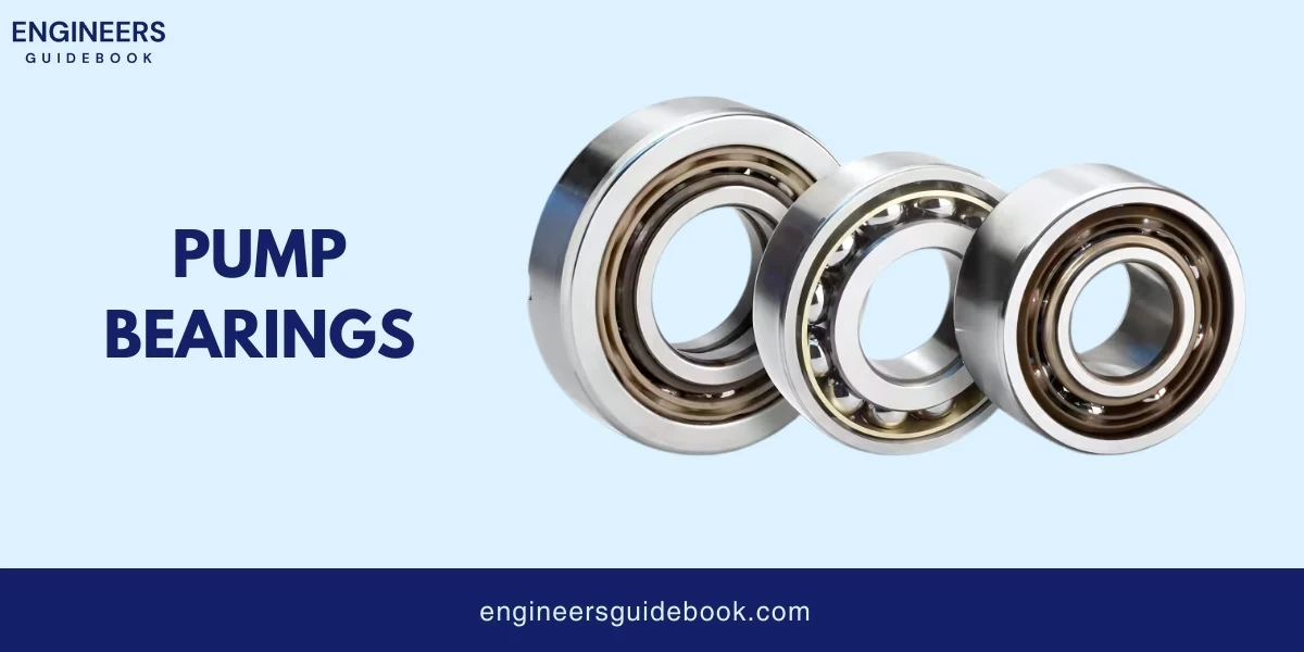
  • Types: Ball bearings, roller bearings, and sleeve bearings are commonly used.
  • Importance: Bearings support the shaft, reduce friction, and ensure smooth rotation. Proper bearing selection and maintenance are crucial for pump reliability and longevity.


Pump bearings

3.5. Seals

Seals prevent fluid from leaking out of the pump casing, ensuring efficient operation and preventing environmental contamination. They also protect internal components from damage due to fluid exposure.
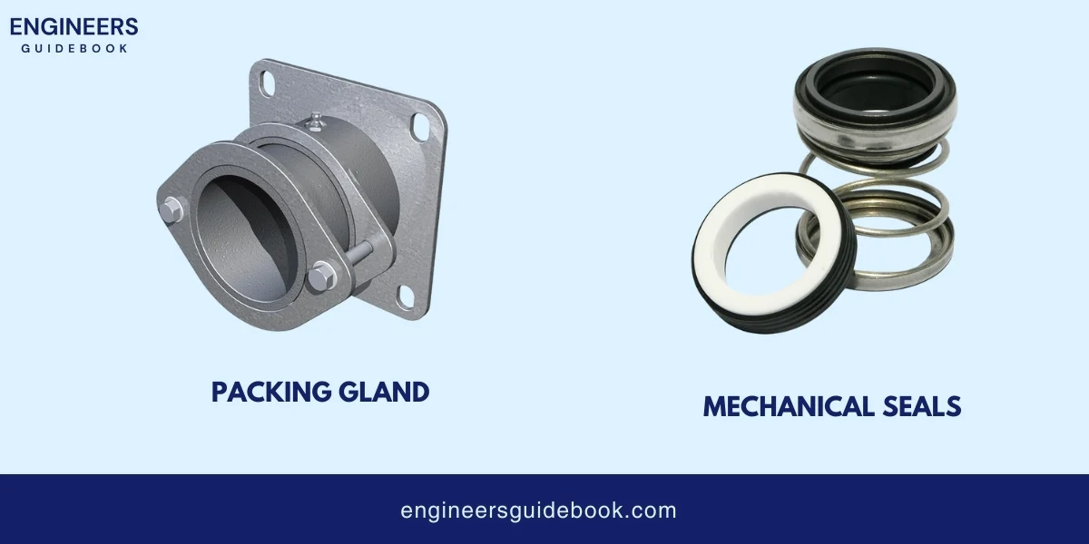
  • Mechanical Seals: Modern and efficient, consisting of a rotating seal ring and a stationary seal ring. Provides a tight seal to prevent leakage.
  • Packing Glands: Traditional sealing method using braided packing material compressed around the shaft. Requires regular maintenance but is simple and cost-effective.


Centrifugal pump seals

3.6. Wear Rings

Wear rings reduce wear between the impeller and casing, maintain efficient performance, and extend the pump’s lifespan.

Wear rings are typically made from hardened metals like stainless steel or bronze, or wear-resistant plastics.

 

Wear ring

3.7. Coupling

Couplings are used to connect the pump shaft to the motor shaft, transmit power, and accommodate misalignment. Couplings help reduce vibration and protect components from damage.
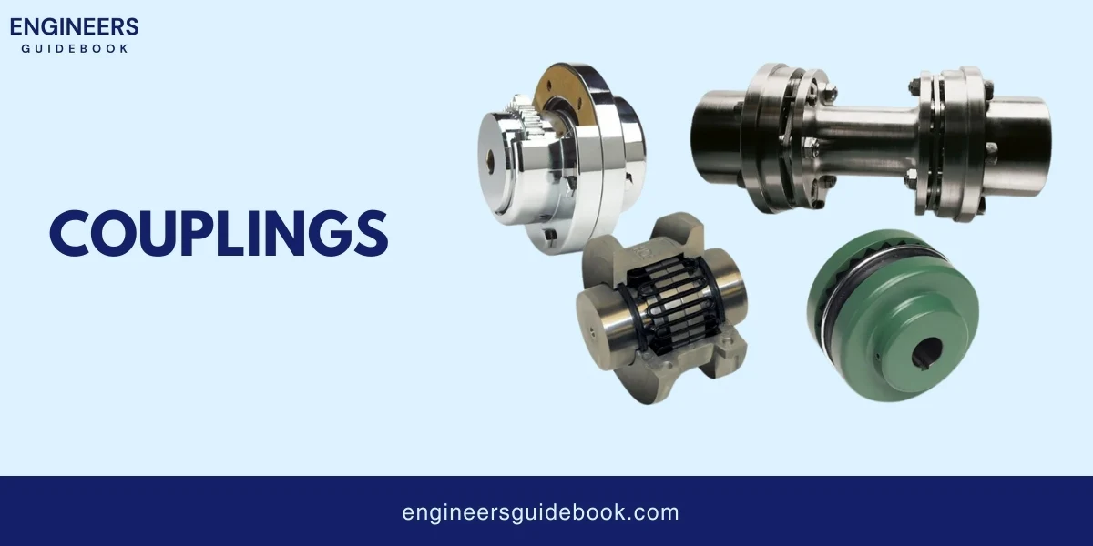
  • Types: Flexible couplings, rigid couplings, and magnetic couplings are common.


Couplings

3.8. Base Plate and Frame

The base Plate and Frame provide stability and support to the pump and motor and ensure proper alignment. They also help reduce vibration and noise.
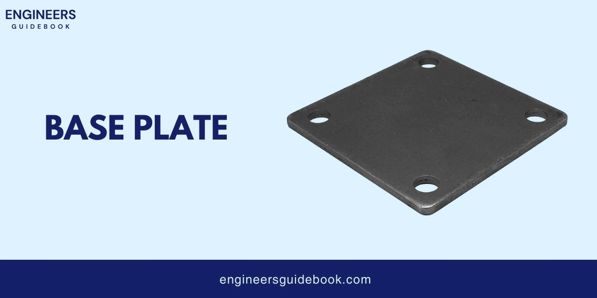
  • Material Considerations: Usually made from steel or cast iron for strength and durability.


Base plate

4. Working Principle of Centrifugal Pumps

A centrifugal pump operates by converting mechanical energy from a motor into kinetic energy in the form of fluid movement. This is achieved by using a rotating impeller that increases the velocity and pressure of the fluid, pushing it through the pump and into the discharge pipe.

4.1. Step-by-Step Process

  • Fluid Entry: Fluid enters the pump through the suction inlet and flows into the center of the impeller, known as the eye.
  • Impeller Rotation: The impeller, driven by a motor, rotates at high speed. This rotation imparts velocity to the fluid.
  • Centrifugal Force: The spinning impeller generates centrifugal force, which pushes the fluid outward from the center to the edges of the impeller.
  • Velocity Increase: As the fluid moves along the impeller vanes, its velocity increases due to the centrifugal force.
  • Fluid Discharge: The fluid exits the impeller at high velocity and enters the pump casing, which guides it towards the discharge outlet.
  • Pressure Conversion: In the casing, the high-velocity fluid’s kinetic energy is converted into pressure energy, enabling the fluid to be discharged at a higher pressure.

4.2. Role of Centrifugal Force

Centrifugal force is the key principle behind the operation of a centrifugal pump. As the impeller rotates, it creates a centrifugal force that pushes the fluid outward from the center of rotation.

This force causes the fluid to move rapidly along the vanes of the impeller, gaining velocity and pressure as it travels. The centrifugal force ensures that the fluid is continuously pushed outward, maintaining a steady flow through the pump.

4.3. Energy Conversion Process

The centrifugal pump’s primary function is to convert mechanical energy from the motor into fluid energy. This involves two main energy conversions:

  • Mechanical to Kinetic Energy: The motor drives the impeller, converting mechanical energy into kinetic energy as the fluid gains velocity.
  • Kinetic to Pressure Energy: As the fluid exits the impeller and enters the pump casing, the kinetic energy is converted into pressure energy, allowing the fluid to be pushed out through the discharge pipe.

4.4. Role of Impeller and Volute

1. Impeller
  • Role: The impeller’s primary role is to increase the fluid’s velocity and create the centrifugal force needed to move the fluid through the pump.
2. Volute
  • Role: The volute’s main role is to convert the fluid’s kinetic energy into pressure energy. The spiral shape of the volute gradually reduces the fluid’s velocity while increasing its pressure, ensuring efficient fluid discharge.

5. Types of Centrifugal Pumps

Types of Centrifugal Pumps
  1. Based on the flow path
  2. Based on the impeller design
  3. Based on stage
  4. Based on the casing split
  5. Special types of centrifugal pumps

5.1. Based on the Flow Path

  1. Radial Flow
  2. Axial Flow
  3. Mixed Flow
1. Radial Flow

In radial flow pumps, the fluid enters the impeller at the center and is discharged perpendicularly to the shaft.

  • Characteristics: High pressure, low flow rate.
  • Applications: Water supply systems, boiler feed applications, and industrial processes.
2. Axial Flow

In axial flow pumps, the fluid flows parallel to the pump shaft, similar to a propeller in a pipe.

  • Characteristics: High flow rate, low pressure.
  • Applications: Flood control, irrigation, and large-scale water circulation.
3. Mixed Flow

Mixed flow pumps combine features of both radial and axial flow pumps. The fluid is discharged at an angle, producing radial and axial components.
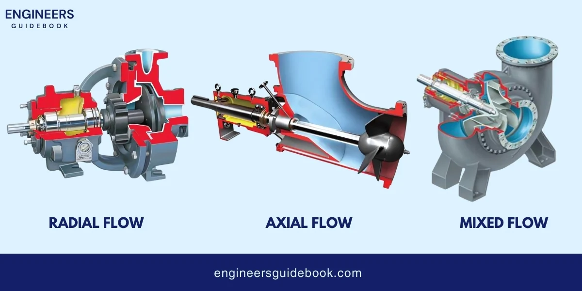
  • Characteristics: Moderate flow rate and pressure.
  • Applications: Cooling water circulation, drainage systems, and sewage treatment.


Centrifugal pump classification according to flow plath

5.2. Based on Impeller Design

1. Open Impeller

Impellers with vanes that are not enclosed by sidewalls are known as open impellers.

  • Characteristics: Easy to clean, handle solids and slurries well.
  • Applications: Wastewater treatment, slurry pumping, and chemical processing.

2. Semi-open Impeller

Impellers with vanes that have one side enclosed.

  • Characteristics: Balance between strength and ease of cleaning.
  • Applications: Industrial processes, food processing, and moderate solids handling.

3. Closed Impeller

 Impellers that are fully enclosed by sidewalls are called closed impellers.

  • Characteristics: High efficiency, suitable for clean fluids.
  • Applications: Water supply, HVAC systems, and oil refineries.


Types of impellers

5.3. Based on Stage Configuration

1. Single-stage

Centrifugal Pumps with only one impeller are called single-stage pumps.

  • Characteristics: Simple design, easy maintenance, and lower cost.
  • Applications: Domestic water pumps, irrigation, and general industry.
2. Multi-stage

Centrifugal pumps that have with multiple impellers in series.
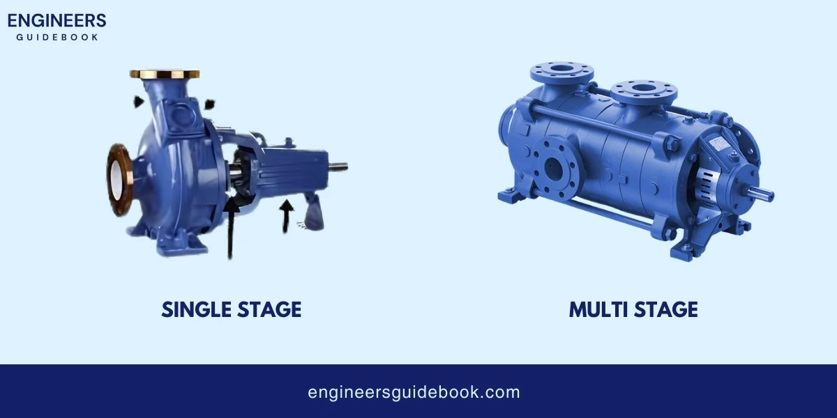
  • Characteristics: High pressure, used for long-distance fluid transfer.
  • Applications: High-pressure cleaning, boiler feed, and mining.


Classification based upon configuration ( single stage and and multistage pump )

5.4. Based on Casing Split

1. Horizontally Split

The casing is split horizontally, making it easy to open and service the pump without disturbing the piping.

  • Characteristics: Easy maintenance and inspection.
  • Applications: Large-scale water supply, power plants, and industrial applications.
2. Vertically Split

The casing is split vertically, often used in high-pressure applications.
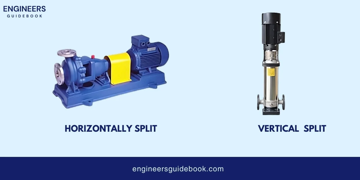
  • Characteristics: Compact design, suitable for high-pressure applications.
  • Applications: Oil and gas industry, petrochemical plants, and high-pressure water supply.


Classification based upon casing split

5.5. Special Types

1. Self-priming Pumps

 Designed to re-prime themselves when initially filled with fluid.

  • Characteristics: Can handle air mixed with fluid, suitable for intermittent flow.
  • Applications: Sewage systems, dewatering, and stormwater management.
2. Submersible Pumps

Designed to operate while fully submerged in the fluid being pumped.

  • Characteristics: Quiet operation, no need for priming, compact.
  • Applications: Deep well pumping, sewage systems, and underwater operations.
3. Magnetic Drive Pumps

Use a magnetic coupling to transmit torque to the impeller without a direct mechanical connection.
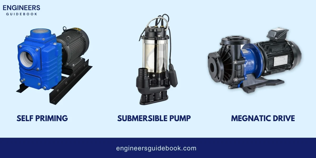
  • Characteristics: Leak-free, suitable for hazardous fluids.
  • Applications: Chemical processing, pharmaceuticals, and hazardous materials handling.


Special types of centrifugal pumps

6. Practical calculations

6.1. Flow Rate (Q) 

Definition:

The flow rate (Q) is the volume of fluid that passes through the pump per unit of time. It is usually measured in cubic meters per hour (m³/h) or gallons per minute (GPM).

Q=A×V

Where:

  • Q = Flow rate
  • A = Cross-sectional area of the pipe (m² or ft²)
  • V = Velocity of the fluid (m/s or ft/s)

6.2. Head (H)

Definition:

The head (H) is the height at which a pump can raise the fluid. It is measured in meters (m) or feet (ft).

H=Pρ × g + V²/2g + Z

Where:

  • H = Head (m or ft)
  • P = Pressure (Pa or psi)
  • ρ = Fluid density (kg/m³ or lb/ft³)
  • g = Acceleration due to gravity (9.81 m/s² or 32.2 ft/s²)
  • V = Velocity of the fluid (m/s or ft/s)
  • Z = Elevation difference (m or ft)

6.3. Power Consumption (P)

Definition: 

The power consumption (P) of a pump is the amount of energy required to move the fluid. It is usually measured in kilowatts (kW) or horsepower (HP).

Where:

  • = Power (W or HP)
  • Q = Flow rate (m³/s or GPM)
  • H = Head (m or ft)
  • ρ= Fluid density (kg/m³ or lb/ft³)
  • g= Acceleration due to gravity (9.81 m/s² or 32.2 ft/s²)
  • η= Pump efficiency 

6.4 Efficiency

The efficiency (η) of a pump is the ratio of the useful power output to the power input.

η= Pout / Pin

Where:

  • η = Efficiency (decimal form)
  • Pout  = Useful power output (W or HP)
  • Pin = Power input (W or HP)

6.5 NPSH (Net Positive Suction Head)

NPSH is a measure of the pressure available at the pump suction to prevent cavitation.

NPSH = Patm / ρ×g + V²/ 2g − Hf − Pv / ρ×g

Where:

  • NPSH = Available NPSH (m or ft)
  • Patm = Atmospheric pressure (Pa or psi)
  • ρ = Fluid density (kg/m³ or lb/ft³)
  • g = Acceleration due to gravity (9.81 m/s² or 32.2 ft/s²)
  • V = Velocity of the fluid (m/s or ft/s)
  • Hf = Head loss due to friction (m or ft)
  • Pv = Vapor pressure of the fluid (Pa or psi)

6.6 Specific Speed

Specific speed is a dimensionless number that describes the geometry of a pump’s impeller.

Ns = N × Sqr. root Q / H³/4

Where:

  • N = Specific speed 
  • N = Rotational speed (RPM)
  • Q = Flow rate (m³/s or GPM)
  • H = Head (m or ft)

7. Advantages of Centrifugal Pumps

Advantages

1. High Flow Rates: Centrifugal pumps are known for their ability to handle high flow rates efficiently.

2. Continuous Flow: One of the significant advantages of centrifugal pumps is their ability to provide a steady and continuous flow of fluid.

3. Low Maintenance: Like gear pumps Centrifugal pumps have a straightforward design with fewer moving parts compared to other types of pumps.

4. Handle Liquids with Suspended Solids: 

Many centrifugal pumps, especially those with open or semi-open impellers, can handle liquids containing suspended solids.

5. Cost-Effectiveness: Centrifugal pumps are cost-effective solutions for high-flow scenarios. Their ability to move large volumes of fluid efficiently reduces energy consumption and operational costs.

6. Wide Range of Applications:

Centrifugal pumps are versatile and can be used in a wide variety of applications.

8. Disadvantages of Centrifugal Pumps

Disadvantages:

1. Limited suction lift capability: Centrifugal pumps cannot effectively lift fluids from deep sources.

2. Potential for cavitation: Cavitation can occur if the pressure at the pump inlet drops too low, causing damage.

3. Reduced efficiency with viscous fluids: High-viscosity fluids decrease the pump’s efficiency and performance.

4. Sensitivity to changes in system conditions: Variations in flow or pressure can significantly affect pump performance.

5. Priming requirements for some designs: Certain centrifugal pumps need to be primed before operation to remove air and ensure proper functioning.

9. Applications of Centrifugal Pumps

Applications:

1. Water supply and distribution: Used to transport water in municipal and residential systems.

2. Wastewater treatment: Employed in the treatment and movement of sewage and industrial waste.

3. Oil and gas industry: Essential for extracting, refining, and transporting oil and gas.

4. Chemical processing: Handles the transfer of various chemicals in industrial processes.

5. Power generation plants: Circulates cooling water and feeds boilers.

6. HVAC systems: Helps circulate water for heating and cooling in buildings.

7. Agriculture and irrigation: Provides water for crop irrigation and livestock.
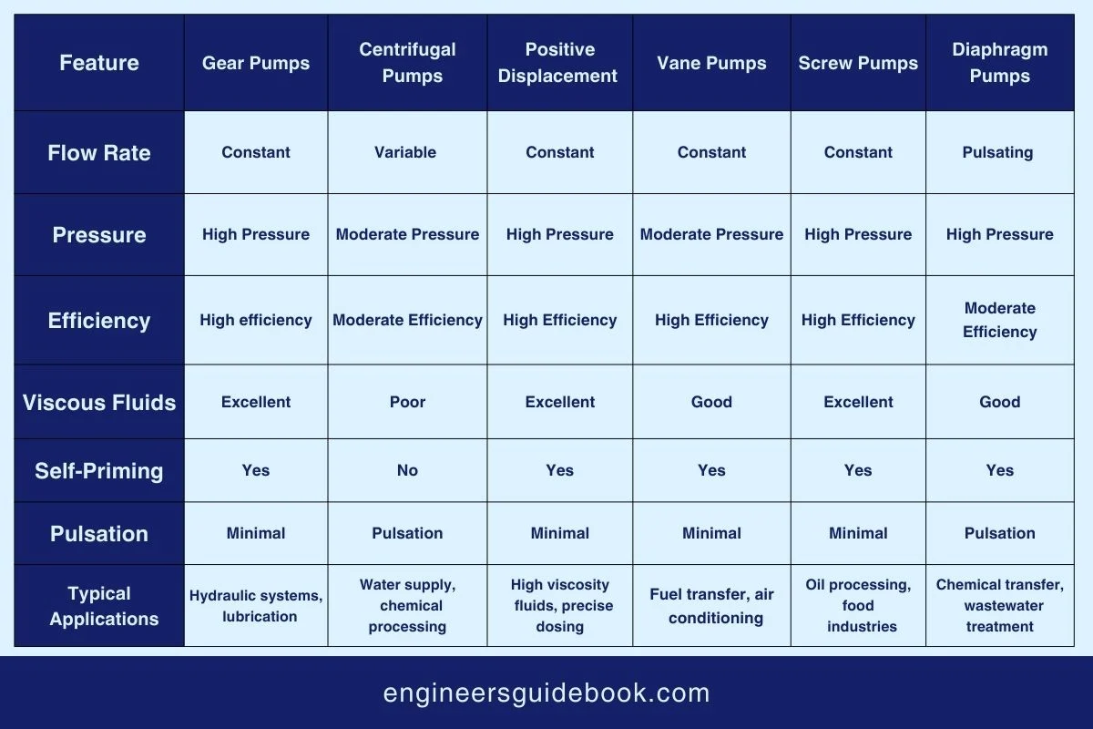
10. Comparison with Other Pump Types

Comparison with other pump types

11. Selection Criteria for Centrifugal Pumps

 1. (Flow Rate, Head, NPSH)
  • Flow Rate: The volume of fluid the pump needs to move in a unit of time.
  • Head: The height the pump needs to move the fluid against gravity.
  • NPSH (Net Positive Suction Head): The required pressure to avoid cavitation (formation of vapor bubbles in a liquid).
2. Fluid Properties 
  • Viscosity: Thickness of the fluid, which affects the pump’s efficiency.
  • Temperature: The heat level of the fluid, influences the material choice to prevent damage.
  • Solid Content: The presence of solid particles that might necessitate a more robust pump design.
3. Environmental Considerations

Factors like ambient temperature, humidity, and potential exposure to chemicals or explosive materials could affect pump operation.

4. Material Compatibility

Ensuring the pump materials (like stainless steel or plastic) are suitable for the fluid and the environmental conditions to avoid corrosion and wear.

5. Energy Efficiency

Selecting a pump that uses the least amount of energy to do the required job, saving costs and reducing environmental impact.

6. Life Cycle Cost Analysis

Considering not just the purchase price but also installation, maintenance, operation, and repair costs over the pump’s lifespan to ensure economic efficiency.

12. Common Issues and Troubleshooting

12.1. Cavitation
  • Causes: Occurs when the pressure in the pump inlet drops below the vapor pressure of the fluid, leading to the formation of vapor bubbles that collapse inside the pump.
  • Effects: This can cause damage to the impeller and reduce pump performance.
  • Solutions: Increase the pressure at the suction side, reduce the pump speed, or ensure the pump is operating within its designed conditions to prevent cavitation.
12.2. Mechanical Seal Failure
  • Causes: Mechanical seal failures can result from improper installation, alignment issues, or running the pump dry.
  • Preventive Measures: Regular inspection and maintenance, ensuring proper installation and alignment, and avoiding dry running of the pump.
12.3. Bearing Failures
  • Causes: Bearing failures often stem from improper lubrication, misalignment, or excessive load.
  • Maintenance Tips: Regularly check and replace lubricants, ensure proper alignment during installation and operation, and monitor load conditions to prevent overloading.
12.4. Vibration and Noise
  • Diagnosing Issues: Excessive vibration and noise can be caused by misalignment, imbalance, or mechanical looseness.
  • Addressing Issues: Realign the pump, balance the impeller, and tighten any loose components. Regular maintenance and monitoring can help diagnose these issues early.
12.5. Loss of Prime
  • Causes: Loss of prime can occur if the pump is not filled with fluid, the suction lift is too high, or there are air leaks in the suction line.
  • Solutions: Ensure the pump is properly primed before starting, check the suction line for air leaks, and make sure the suction lift is within design limits.

13. Installation and Maintenance

1. Proper Installation Practices
  • Foundation: Ensure the pump is mounted on a stable and level foundation to prevent vibration and misalignment.
  • Piping: Use the correct size and type of piping to avoid strain on the pump housing and ensure there are no leaks in the suction and discharge lines.
2. Alignment and Balancing
  • Alignment: Properly align the pump with the driving motor to prevent excessive wear and tear on bearings and couplings.
  • Balancing: Ensure the impeller and rotating elements are balanced to minimize vibration, which can extend the life of the pump.
3. Monitoring and Diagnostics
  • Vibration Analysis: Regularly monitor vibration levels to detect abnormalities that indicate misalignment or bearing failures.
  • Temperature Monitoring: Keep track of bearing and seal temperatures to identify overheating, which can be a sign of lubrication issues or mechanical failure.
  • Pressure Gauges: Install pressure gauges on the suction and discharge sides to monitor pump performance and detect conditions like cavitation or blocked filters.
4. Common Maintenance Tasks
  • Lubrication: Regularly check and change the lubricant in bearing housings to ensure smooth operation and prevent overheating.
  • Seal Replacement: Inspect mechanical seals periodically for wear and replace them as needed to prevent leaks.
  • Impeller Inspection: Check the impeller for wear and damage, especially if the pump handles abrasive or corrosive fluids.
5. Troubleshooting Common Issues
  • Cavitation: Look for signs of pitting or erosion on the impeller and listen for abnormal noises; adjust the system to minimize the drop in pressure at the pump inlet.
  • Loss of Prime: Check for air leaks in the suction line and ensure the pump is adequately primed to maintain suction pressure.
  • Excessive Vibration: Realign and rebalance the pump, check for worn or damaged components, and ensure that all bolts are tightened properly.

14. Case Studies

Water Treatment Plant in California
  • Situation: A municipal water treatment plant in California needed to upgrade its aging infrastructure to meet increasing demand and regulatory standards.
  • Solution: The plant installed high-efficiency centrifugal pumps to handle the increased volume of water. These pumps were equipped with variable frequency drives (VFDs) to optimize energy use.
  • Outcome: The upgrade resulted in a 20% increase in water treatment capacity and a 15% reduction in energy consumption, helping the plant meet environmental regulations and save on operational costs.
Oil Refinery in Texas
  • Situation: An oil refinery in Texas faced challenges with its existing pumps due to frequent cavitation and mechanical seal failures, leading to downtime and maintenance costs.
  • Solution: The refinery replaced the problematic pumps with advanced centrifugal pumps designed to handle high-pressure and high-temperature fluids. The new pumps had improved seal designs and better NPSH characteristics.
  • Outcome: The refinery saw a significant decrease in downtime, a reduction in maintenance costs by 30%, and improved overall efficiency in its operations.

15. Problem-Solving Examples

Addressing Cavitation in a Chemical Plant
  • Problem: A chemical plant experienced cavitation in their centrifugal pumps, causing damage to the impellers and reducing pump efficiency.
  • Analysis: Engineers conducted a thorough analysis and found that the suction head was too low, causing vapor bubbles to form and collapse in the pump.
  • Solution: The plant increased the suction head by raising the fluid level in the supply tank and installed a booster pump to increase inlet pressure. They also upgraded to pumps with better NPSH characteristics.
  • Result: The cavitation issue was resolved, leading to increased pump life and consistent performance, reducing maintenance costs and production downtime.
Improving Efficiency in an Agricultural Irrigation System
  • Problem: An agricultural irrigation system faced inefficiencies with high energy consumption and uneven water distribution.
  • Analysis: It was found that the existing pumps were not optimally sized for the system’s requirements, and there was a significant loss of pressure due to friction in the piping.
  • Solution: The irrigation system was re-engineered to include properly sized centrifugal pumps with VFDs for better control of flow rates. The piping was upgraded to reduce friction losses.
  • Result: The improvements led to a 25% reduction in energy consumption and more uniform water distribution across the fields, enhancing crop yields and lowering operational costs.

16. Conclusion

Centrifugal pumps are essential components in various industries due to their ability to handle high flow rates, provide steady continuous flow, and operate with a simple design.

Key aspects such as proper installation, alignment, regular monitoring, and maintenance are crucial for their optimal performance.

Addressing common issues like cavitation, mechanical seal failure, and bearing failures through proper troubleshooting enhances the longevity and reliability of these pumps.

FAQ

What is a centrifugal pump and how does it work?

A centrifugal pump is a mechanical device that uses rotational energy to move fluid through a system. It operates by converting rotational kinetic energy, typically from a motor, into hydrodynamic energy of the fluid flow.

The main components include the impeller, casing, shaft, bearings, and mechanical seal. The impeller transfers energy to the fluid, while the casing directs the flow.

Efficiency is calculated using the formula:

Efficiency = Output Power / Input Power × 100 

Output power is the hydraulic power delivered to the fluid, and input power is the power supplied to the pump.

Centrifugal pumps are used in water supply systems, sewage treatment, chemical processing, oil and gas industries, irrigation, and HVAC systems.

Selection depends on factors like fluid type, flow rate, pressure requirements, and system design. Consult pump performance curves and specifications to choose the right model.

Single-stage pumps have one impeller, suitable for low-pressure applications. Multi-stage pumps have multiple impellers, increasing pressure output for high-pressure applications.

Regular maintenance includes checking for leaks, inspecting bearings and seals, ensuring proper lubrication, and cleaning the impeller and casing.

Common issues include cavitation, overheating, and leaks. Troubleshooting tips involve checking for blockages, ensuring proper alignment, and verifying fluid levels.

Impeller design influences the flow rate and pressure. Different designs, like radial, axial, or mixed-flow impellers, are chosen based on the specific application and performance requirements.

Ensure proper installation, follow manufacturer guidelines, wear appropriate personal protective equipment (PPE), and regularly inspect and maintain the pump.

Cavitation occurs when vapor bubbles form in the liquid being pumped, often due to low pressure or high temperature, causing noise and potential damage to the impeller.

The volute is the casing that collects fluid discharged by the impeller, converting kinetic energy into pressure energy.

NPSH required is specified by the pump manufacturer and indicates the minimum pressure required to prevent cavitation.

Author

Muhammad ali
Muhammad Ali

Muhammad Ali holds a PhD in Mechanical Engineering from MIT and is currently conducting groundbreaking research on sustainable energy systems. His innovative work in renewable energy integration has earned him numerous accolades in the engineering community.

Facebook
Twitter
LinkedIn
WhatsApp

Sign up for our Newsletter