June 23, 2024 By Usman Ahmed 8 minutes read
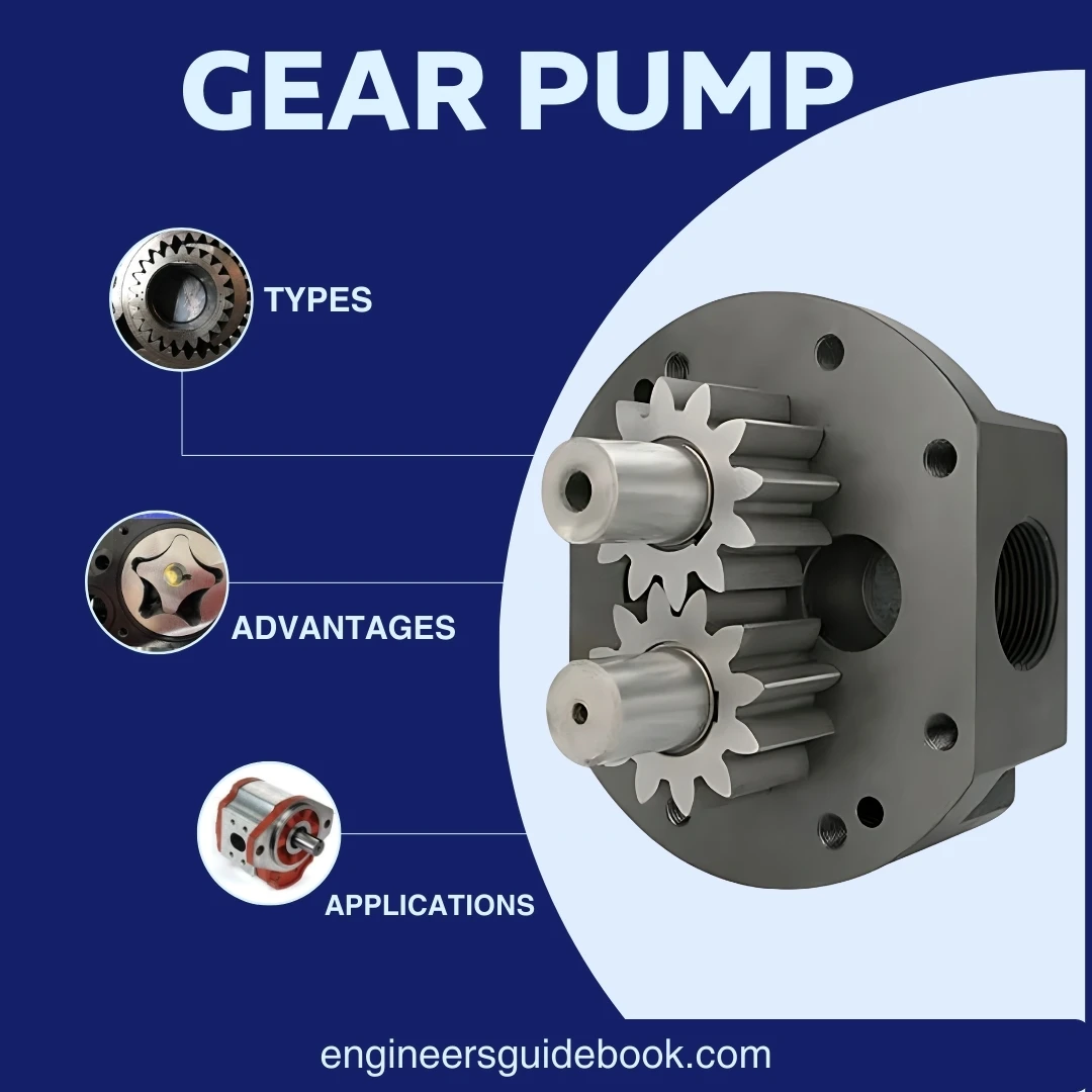
A gear pump is vital in various industrial applications and is known for its efficiency and reliability in transferring fluids. As you know, a gear pump is a positive displacement pump that operates through the meshing of gears, which creates a continuous flow of liquid. Gear pumps are one of the most common types of pumps for hydraulic fluid power applications.
In this blog post, we will explore the fundamental principles of gear pumps, their types, and their advantages in different industries. So, let us first define what is a gear pump.
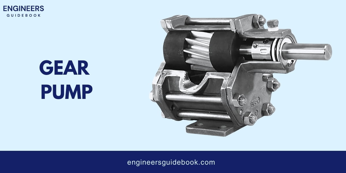
Gear pumps are a type of pump that moves fluids by using interlocking gears to pump the liquid through the system. These pumps generally consist of two gears that rotate against each other, creating a vacuum at the pump inlet to draw in the fluid. As the gear rotates, fluid moves out.
The concept of gear pumps dates back to the early 1600s. The first gear pump was created in the 16th century by a German engineer named Johannes Kepler.
Significant development in their design and application began in the late 19th century. Originally, these pumps were designed for transporting water, but as industries evolved, so did the applications of gear pumps. They became essential in transferring a variety of fluids in many industrial processes.
Gear pumps move fluids using two gears that work together. Here’s how they work:
The casing of a gear pump is typically made from materials like cast iron, stainless steel, or aluminum, depending on the type of fluid being pumped and the operating conditions.
Bearings and bushings support the rotating shafts of the gears and reduce friction, which helps in the smooth operation of the pump.
Seals and gaskets are used to prevent fluid leaks from the pump. They ensure that the fluid stays within the designated pathways inside the pump.
The shafts connect the gears to the motor and transmit the rotational power needed to drive the gears.
End plates are used to keep all the components of the pump aligned and in place. They help maintain the correct positioning of the gears and other internal parts.

There are two main types of gear pumps.
There are generally two main types of gear pumps used in industry.
External gear pumps are also divided into types.
Spur gear pumps are the most common type of external gear pumps. They use two identical gears with straight teeth that rotate in opposite directions.
The fluid is trapped between the teeth and the casing and moved from the inlet to the outlet. These pumps are known for their simplicity and efficiency, making them ideal for various applications.

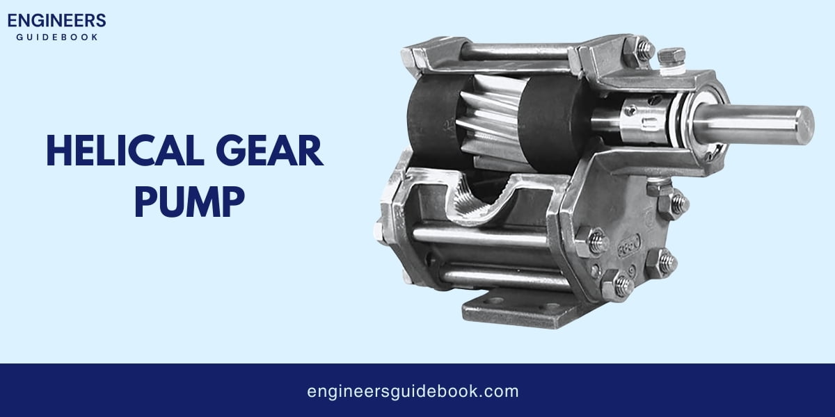
Helical gear pumps use gears with angled teeth. Compared to spur gears, the angled teeth provide smoother and quieter operation.
The fluid movement is similar, trapped between the gear teeth and the casing, but the helical design reduces pulsation and noise. These pumps are often used in applications where noise reduction is essential.
Internal gear pumps are also divided into types.
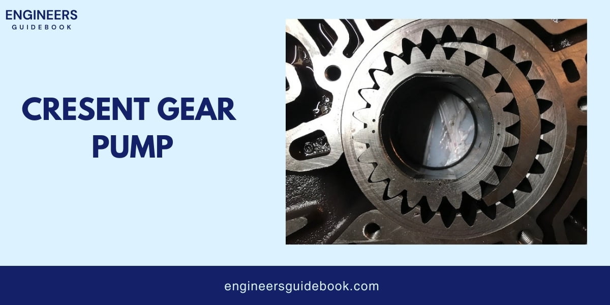
Crescent gear pumps have an internal and external gear separated by a crescent-shaped partition. The internal gear rotates inside the outer gear, and the crescent helps to create a seal between the inlet and outlet.
Fluid is trapped in the spaces between the gears and the crescent and then moved from the inlet to the outlet. These pumps are known for their ability to handle viscous fluids and their smooth, quiet operation.
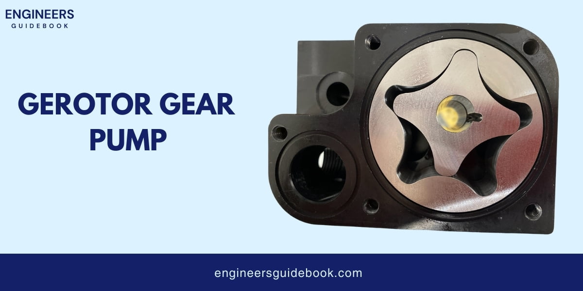
Gerotor pumps consist of an inner and outer rotor with different numbers of teeth. The inner rotor has one less tooth than the outer rotor and is mounted off-center.
As the inner rotor turns, the outer rotor rotates, creating a series of expanding and contracting cavities that move the fluid from the inlet to the outlet.
Gerotor pumps are compact and efficient, making them suitable for a variety of applications, especially where space is limited.
1. High Efficiency: Gear pumps can move a large amount of fluid with minimal energy loss.
2. Self-Priming Capability: Gear pumps can start pumping without needing to be filled with fluid first.
3. Consistent Flow Rate: Gear pumps provide a steady and reliable fluid delivery.
4. Ability to Handle High-Viscosity Fluids: Gear pumps can easily move thick, dense fluids.
5. Compact Design: Gear pumps are ideal for use in limited spaces due to their small size.
6. Low Maintenance Requirements: Gear pumps require minimal maintenance because of their sturdy construction.
7. Reversible Flow Direction: Gear pumps can pump fluid in either direction.
1. Limited Ability to Handle Abrasive Fluids : Gear pumps can wear out quickly when used with abrasive fluids.
2. Potential for Cavitation: Gear pumps can experience cavitation if not properly managed.
3. Noise and Vibration Issues: Gear pumps can produce significant noise and vibration during operation.
4. Limited Pressure Capabilities: Gear pumps may not achieve as high pressures as other pump types.
5. Temperature Sensitivity: Gear pumps can be sensitive to temperature changes, affecting performance
1. Automotive Industry: Gear pumps are used in automotive engines for lubrication and fuel injection.
2. Chemical Processing: Gear pumps are utilized for handling and transferring chemicals and solvents.
3. Oil and Gas Industry: Gear pumps are essential for transporting crude oil, lubricants, and refined products.
4. Food and Beverage Industry: Gear pumps are used for moving syrups, oils, and other food-grade liquids.
5. Pharmaceuticals: Gear pumps are employed to produce and transfer medicinal liquids and ingredients.
6. Hydraulic Systems: Gear pumps are key components in hydraulic systems for machinery and equipment.
The flow rate Q of a gear pump can be calculated using the formula:
Q=n×V×ηQ
Where:
The pressure P of a gear pumps can be calculated using the formula:
P = T×2×π / V×ηm
Where:
The velocity V of the fluid can be calculated using the formula:
V = Q \ A
Where:
Net Positive Suction Head (NPSH) is essential to prevent cavitation. The pump manufacturer specifies the NPSH required (NPSHr), which must be less than the NPSH available (NPSHa) in the system to ensure proper operation.
The power P consumed by a gear pump can be calculated using the formula:
P= Q × P diff / ηoverall
Where:
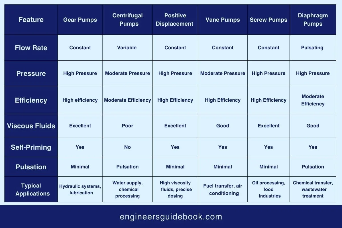
Proper maintenance and troubleshooting are essential to ensure their optimal performance and longevity in gear pumps.
Gear pumps are integral to many industries due to their simplicity, reliability, and efficiency. External gear pumps, known for high pressure and flow rate capabilities, are ideal for industrial applications.
With their smooth and quiet operation, internal gear pumps handle various fluids, making them perfect for precise flow control tasks.
Despite their advantages, such as easy maintenance and versatility, gear pumps face challenges like wear and limited suction lift.
They are widely used to handle viscous fluids in automotive oil pumps, industrial chemical processing, and food and beverage applications.
Understanding these aspects ensures informed decisions, optimizing efficiency and reliability across various applications.
A gear pump is a positive displacement pump that uses interlocking gears to move fluids. It operates through the meshing of gears, creating a continuous flow of liquid.
There are two main types of gear pumps: external gear pumps and internal gear pumps. External gear pumps include spur and helical gear pumps, while internal gear pumps include crescent and gerotor gear pumps.
External gear pumps use two identical gears with straight or angled teeth that rotate in opposite directions. The fluid is trapped between the teeth and the casing and moved from the inlet to the outlet.
Internal gear pumps have an internal and external gear separated by a partition. The internal gear rotates inside the outer gear, trapping fluid in the spaces between the gears and the partition, moving it from the inlet to the outlet.
Gear pumps are classified into two main types: external gear pumps and internal gear pumps.
External Gear Pumps: These pumps consist of two external gears that mesh outside the pump casing. Fluid is carried between the gear teeth and the casing to the discharge port.
Internal Gear Pumps: Internal gear pumps have an internal and external gear set configuration. Fluid enters the pump inlet and is carried between the teeth of the internal gear and the crescent-shaped internal housing to the discharge port.
Gear pumps are favored for their simple design, reliability, and ability to handle a wide range of fluids efficiently. They offer compact size, cost-effectiveness, and smooth, pulsation-free flow, making them ideal for various industrial applications.
Disadvantages of gear pumps include limited efficiency at high pressures, the potential for fluid leakage due to clearance gaps, and sensitivity to viscosity changes, which can affect performance.
Gear pumps are commonly used in hydraulic systems for machinery and vehicles, chemical processing for handling viscous fluids, and food processing for gentle product handline.
Gear pump casings are typically made from materials such as cast iron, stainless steel, aluminum, or various types of engineered plastics (like polyamide or PTFE).
The principle of a gear pump involves using the meshing of gears to create a fluid flow. As gears rotate, they create suction at the inlet, trapping fluid between the gear teeth and casing.
This trapped fluid is carried around the gears to the outlet, where it is discharged due to the continuous meshing and unmeshing of the gear teeth.
Gear pumps use gears’ meshing to create a pumping action. As gears rotate, they draw in fluid at the inlet side, trap it between the gear teeth and the pump casing, and then push it out through the discharge side as the gears continue to rotate, creating a continuous flow of fluid.
he maximum pressure for a gear pump typically ranges from 250 psi (pounds per square inch) to 500 psi, depending on the design, size, and materials used in construction.
oise and vibration in gear pumps can be caused by:

Muhammad Ali holds a PhD in Mechanical Engineering from MIT and is currently conducting groundbreaking research on sustainable energy systems. His innovative work in renewable energy integration has earned him numerous accolades in the engineering community.
Explore the Engineer’s Guidebook! Find the latest engineering tips, industry insights, and creative projects. Get inspired and fuel your passion for engineering.
© 2023-2024 Engineer’s Guidebook. All rights reserved. Explore, Innovate, Engineer.