May 28, 2024 By Muhammad Ali 8 minutes read
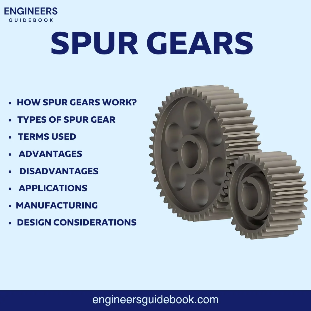
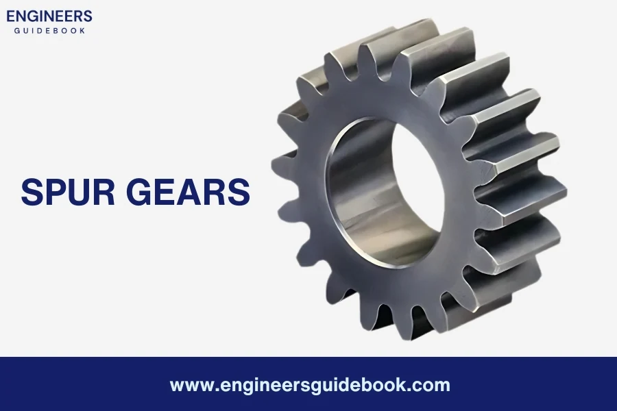
Spur gears are one of the simplest and most common types of gears used in various mechanical systems. They are characterized by their straight teeth, which are mounted on a parallel shaft. These teeth interact with other gears to transmit motion and power efficiently.
Their simple design makes them highly efficient for transmitting power and motion between parallel shafts. This efficiency, combined with their ease of manufacturing and cost-effectiveness, makes them a go-to choice for many applications.
In this article, you’ll learn in detail about spur gears, understanding of their structure, types, advantages, disadvantages, and various applications.
A spur gear is a type of gear with straight teeth that are mounted on a parallel shaft, used to transmit motion and power efficiently between two rotating shafts.
Spur gears transmit motion and power through the meshing of their teeth. Here’s a step-by-step explanation of the process:
When two spur gears are placed side by side, their teeth come into contact.
As one gear (the driver) rotates, its teeth push against the teeth of the other gear (the driven gear).
This contact must be smooth and consistent to ensure efficient power transmission.
The driver gear exerts a force on the driven gear at the point where their teeth mesh.
This force is transmitted along the line of action, which is the line that runs tangential to the base circles of the gears.
The line of action is crucial because it determines the direction and magnitude of the force being transferred.
The force exerted by the driver gear generates torque in the driven gear, causing it to rotate.
The ratio of the number of teeth between the driver and driven gears determines the gear ratio, which in turn affects the torque and speed of the driven gear.
For example, if the driver gear has 20 teeth and the driven gear has 40 teeth, the gear ratio is 1:2. This means the driven gear will rotate at half the speed of the driver gear but with twice the torque.
As the driver gear continues to rotate, each successive tooth engages with the corresponding tooth on the driven gear.
This continuous engagement ensures a steady transmission of motion and power. The teeth must be precisely machined and aligned to maintain smooth operation and avoid slippage or excessive wear.
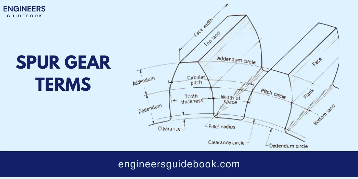
Understanding the terminology associated with spur gears is essential for grasping their design, operation, and application. Here are ten important terms you should know:
Pitch Circle: The imaginary circle that passes through the points where the teeth of two meshing gears make contact. It is used as a reference point for gear calculations.
Pitch Diameter: The diameter of the pitch circle. It is a crucial dimension used to determine the size and spacing of the gear teeth.
Module: A measure of the size of the gear teeth, defined as the pitch diameter divided by the number of teeth. It is used to standardize gear dimensions.
Pressure Angle: The angle between the line of action (where the force is transmitted between teeth) and the tangent to the pitch circle. Common pressure angles are 20° and 14.5°.
Addendum: The radial distance between the pitch circle and the top of the gear teeth. It represents the height of the teeth above the pitch circle.
Dedendum: The radial distance between the pitch circle and the bottom of the gear teeth. It represents the depth of the tooth space below the pitch circle.
Backlash: The slight gap between the teeth of meshing gears. It allows for lubrication and thermal expansion but must be controlled to avoid excessive play and noise.
Tooth Profile: The shape of the gear teeth, usually designed as an involute curve to ensure smooth and consistent engagement and transmission of motion.
Face Width: The width of the gear teeth measured along the axis of the gear. It affects the gear’s strength and load-carrying capacity.
Gear Ratio: The ratio of the number of teeth on the driven gear to the number of teeth on the driver gear. It determines the relative speeds and torques of the gears in a system.
Spur gears come in various types, each designed for specific applications and offering unique benefits. Understanding these different types will help you select the right gear for your needs.
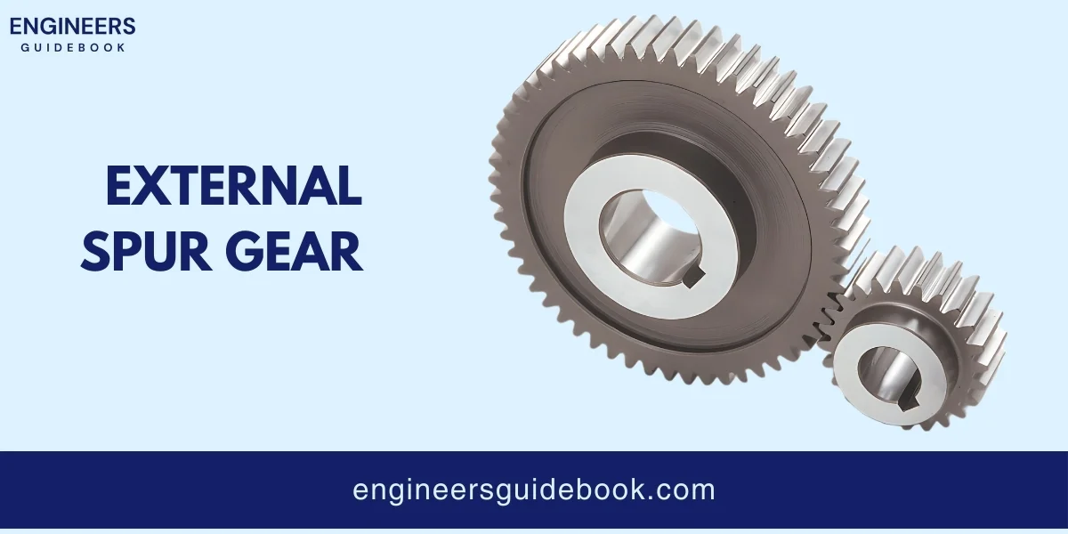
External spur gears are the most common type of spur gear. They have teeth cut on the outside surface of the gear wheel. When two external spur gears mesh, they rotate in opposite directions. This type of gear is widely used due to its simplicity and efficiency.
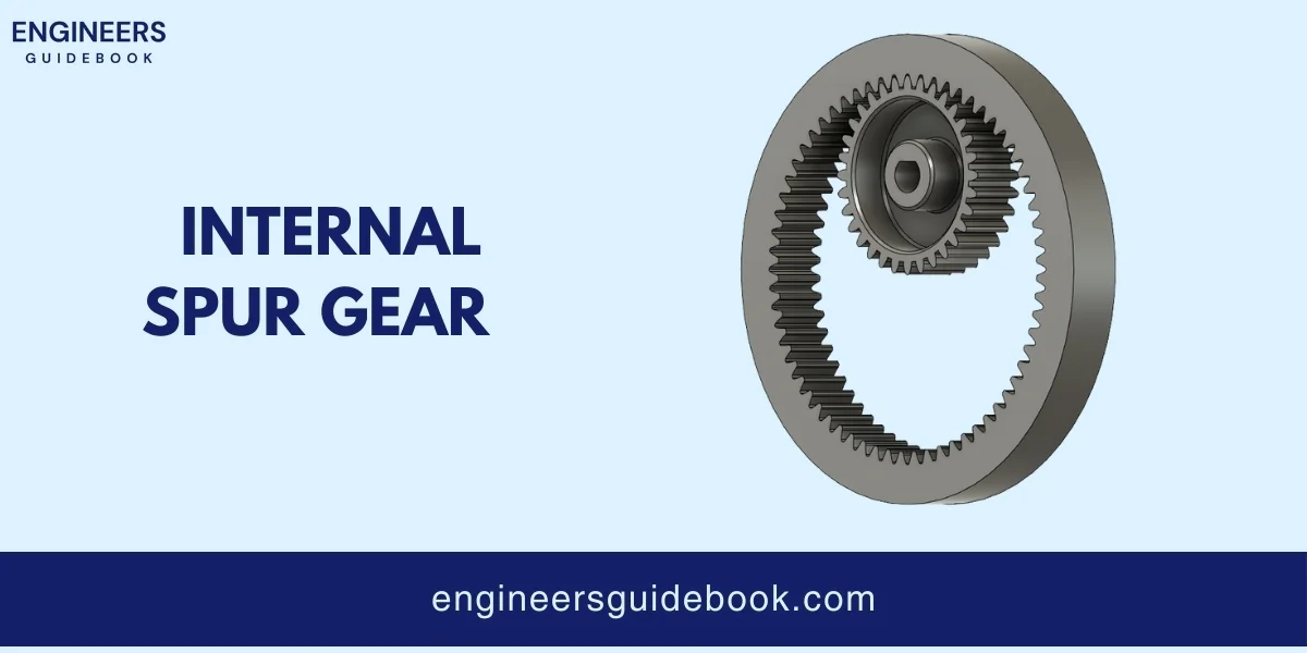
Internal spur gears have teeth cut on the inside surface of the gear wheel. When meshed with an external spur gear, both gears rotate in the same direction. This configuration allows for a more compact design and is often used in planetary gear systems.
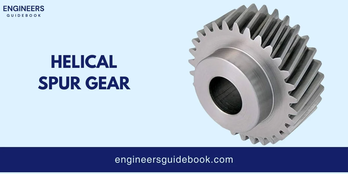
Helical spur gears have teeth that are cut at an angle to the axis of rotation. This design allows for smoother and quieter operation compared to straight-cut spur gears. The angled teeth engage gradually, reducing shock loads and noise.
Efficiency: Because of their simple design and direct tooth engagement, they transmit power with minimal energy loss.
Simplicity and Cost: Their simple construction not only makes them easy to manufacture but also reduces production costs.
Reliability: Spur gears are highly reliable due to their robust construction and durable materials.
No Axial Thrust: Unlike helical gears, spur gears do not generate axial thrust because their teeth are parallel to the gear axis.
Versatility: From small precision instruments to large industrial machines, spur gears can be adapted to fit various sizes, loads, and operational requirements.
Precision: The straightforward design of spur gears allows for precise manufacturing. This precision ensures that spur gears can achieve accurate and consistent motion transmission.
Noise: Because spur gears have straight teeth that engage abruptly, they tend to produce more noise compared to other types of gears, such as helical gears.
Load Distribution: Spur gears tend to distribute loads unevenly across their teeth. This is due to the way their teeth engage all at once, rather than gradually. As a result, the teeth can experience higher stress concentrations.
Axial Forces: Radial forces can cause deflection in the shafts and bearings, potentially leading to misalignment and additional wear.
Limited Speed Capability: Due to the way spur gears engage and disengage their teeth, they are generally less capable of handling very high speeds.
Efficiency Reduction Under Misalignment: Spur gears require precise alignment to operate efficiently. Even slight misalignments can lead to a reduction in efficiency, increased noise, and accelerated wear.
Heat treatment is a vital process in gear manufacturing that enhances the hardness and strength of the gear material. By altering the microstructure of the material, heat treatment improves the gear’s wear resistance and load-carrying capacity.
The load capacity of a spur gear is the maximum force it can transmit without failing. This involves calculating the gear’s contact stress, which depends on the material properties, gear dimensions, and operating conditions.
The choice of material significantly impacts the load capacity. High-strength materials like alloy steels can handle greater loads.
Larger teeth can distribute loads more evenly, reducing stress concentrations. Proper tooth profile design also enhances load distribution.
Factors such as temperature, lubrication, and speed affect load capacity. Maintaining optimal operating conditions ensures gears can handle their designed loads efficiently.
The gear ratio is the ratio of the number of teeth on the driven gear to the number of teeth on the driver gear. It determines the relative speeds and torques of the gears.
Selecting the correct gear ratio is crucial for achieving the desired performance in terms of speed and torque.
Spur gears are fundamental components in many mechanical systems, offering simplicity, efficiency, and reliability. By understanding their basic structure, operating principles, types, advantages, disadvantages, and applications, you can make informed decisions when selecting and designing gear systems for various applications. From automotive transmissions to industrial machinery, spur gears play a crucial role in ensuring smooth and efficient power transmission. Keeping in mind the design considerations and manufacturing processes will help you optimize their performance and longevity.
Thank you for joining me on this journey through the world of spur gears. Whether you’re a student or a professional, I hope this guide has provided you with valuable insights and a deeper understanding of these essential mechanical components.
Shigley, Joseph E., and Charles R. Mischke. “Mechanical Engineering Design.”
Oberg, Erik, et al. “Machinery’s Handbook.”
American Gear Manufacturers Association (AGMA) Standards.
Drago, Raymond J. “Fundamentals of Gear Design.”
Dudley, Darle W., ed. “Gear Handbook: The Design, Manufacture, and Application of Gears.”
A spur gear is a type of gear with straight teeth mounted on a parallel shaft, used to transmit motion and power efficiently between two rotating shafts.
Spur gears work by meshing their teeth with those of another gear, transmitting torque and rotational motion from one gear to the other.
Advantages include high efficiency, simplicity, cost-effectiveness, reliability, and the absence of axial thrust.
Disadvantages include noise generation, uneven load distribution, radial forces, limited speed capability, and sensitivity to misalignment.
They are used in various applications, including automotive transmissions, industrial machinery, robotic systems, consumer electronics, and aerospace instruments.
Common materials include steel, brass, and plastic, chosen based on the application’s load requirements, durability, and environmental conditions.
Spur gears have straight teeth and produce more noise, while helical gears have angled teeth, resulting in smoother and quieter operation but generating axial thrust.
Manufacturing methods include hobbing, milling, and shaping, with additional processes like heat treatment and precision machining to ensure quality and performance.
The pitch circle is an imaginary circle that passes through the points where the teeth of meshing gears make contact.
The pressure angle is the angle between the line of action (force transmission line) and the tangent to the pitch circle, typically 20° or 14.5°.
The module is a measure of the size of the gear teeth, defined as the pitch diameter divided by the number of teeth.
The gear ratio is calculated by dividing the number of teeth on the driven gear by the number of teeth on the driver gear.
Backlash is the small gap between the teeth of meshing gears, allowing for lubrication and thermal expansion but needing control to avoid excessive play.
Noise is caused by the abrupt engagement of straight teeth, resulting in vibration and impact during operation.

Muhammad Ali holds a PhD in Mechanical Engineering from MIT and is a writing specialist. His groundbreaking research on sustainable energy systems and renewable energy integration has earned him numerous accolades. His passion for innovation and education shines through in his insightful and inspiring writings.
Explore the Engineer’s Guidebook! Find the latest engineering tips, industry insights, and creative projects. Get inspired and fuel your passion for engineering.
© 2023-2024 Engineer’s Guidebook. All rights reserved. Explore, Innovate, Engineer.
7 Responses
It’s amazing in favor of me to have a website, which is beneficial for my knowledge.
thanks admin
Hi there to every body, it’s my first pay a visit of this website;
this web site carries awesome and truly fine
stuff in support of visitors.
It’s amazing in favor of me to have a website, which is valuable designed for my know-how.
thanks admin
Amazing! This blog looks exactly like my old one!
It’s on a completely different topic but it has pretty much the same layout and design. Great choice of
colors!
Article writing is also a fun, if you be acquainted with then you
can write if not it is complex to write.
Some genuinely nice and utilitarian information on this web site, too I conceive the style and design holds wonderful features.
I have been exploring for a little bit for any high-quality articles or weblog posts in this kind of area . Exploring in Yahoo I finally stumbled upon this website. Studying this information So i am glad to convey that I have an incredibly good uncanny feeling I found out just what I needed. I most indubitably will make certain to do not disregard this site and give it a glance regularly.