Search

Types of Gears | Advantages, Disadvantages And Uses |

Types of Gears | Advantages, Disadvantages And Uses |

May 28, 2024       By Muhammad Ali            8 minutes read
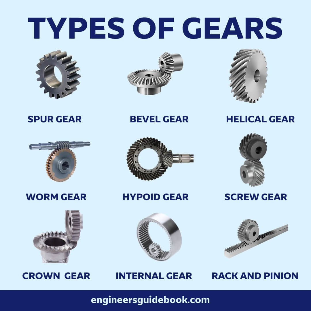
Types of gears

Table of Contents

Facebook
Twitter
LinkedIn
WhatsApp

Introduction

Chain drive, belt drive, gear drive, and rope drive are all mechanisms used to transmit power and motion between different components. One similarity among these drives is their ability to transfer energy from a driving source to a driven element. While each drive has its unique characteristics and applications, they all share the fundamental function of power transmission in various mechanical systems.

In this article we will discuss in detail about TYPES OF GEARS ADDVANTAGES, DISADVANTAGES AND USES.

So, let us first define what is a gear ?

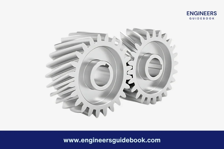
Gears are wheels that have projections (called teeth) as shown in fig are provided on the periphery of wheel A which will fit into the corresponding recesses on the periphery of wheel B. A friction wheel with teeth cut on it is known as gear or toothed wheel.
Types of gears

There are 2 basic functions of gears due to which gears are fundamental components in a wide range of mechanical systems, from simple machines to complex industrial equipment.

  • Gears are used to transmit the exact velocity ratio.
  • Gears are used to transmit power between the shafts.

By altering the size and number of teeth on the gears, engineers can control the speed and direction of the equipment. Gears are essential in ensuring the smooth and efficient operation of various machines and devices.

Classification of gears

1. According To Axes of The Shafts

  1. Parallel and Co-Planar Shafts
  2. Intersecting and Coplanar Shafts
  3. Non-Intersecting, Non-Parallel, and Non-Coplanar Shafts
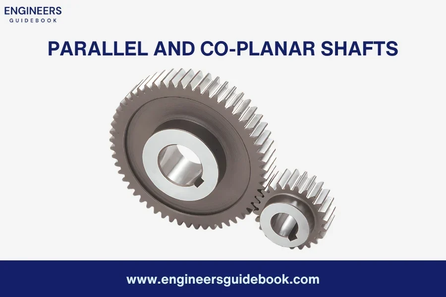
Parallel and Co-Planar Shafts

In below Figure, you can see a visual representation of two shafts that run parallel and lie within the same plane (co-Planar) . These shafts are connected by gears known as spur gears. Spur gears have teeth that are aligned parallel to the axis of the wheel, providing efficient power transmission. Additionally, when the teeth of spur gears are inclined to the axis, they are referred to as helical gears, which offer distinct advantages in certain applications.
Parallel and co-planar shaft gears
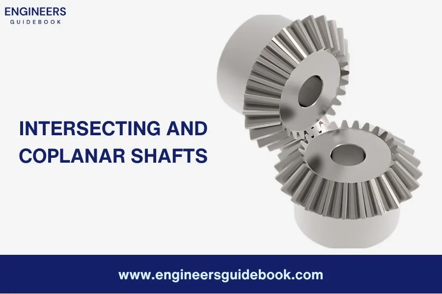
Intersecting and Coplanar Shafts

In the figure, you can observe two shafts that are not parallel but intersect each other within the same plane. Gears connecting these shafts are called bevel gears, and the arrangement is known as bevel gearing. Bevel gears, similar to spur gears, can have their teeth inclined to the face of the bevel, and in such cases, they are referred to as helical bevel gears.
Intersecting and coplanar shaft gears
Non-Intersecting Non-Coplanar Shafts

The figure illustrates two shafts that do not intersect and are neither parallel nor coplanar. Gears connecting these shafts are called skew bevel gears or spiral gears, and the arrangement is known as skew bevel gearing or spiral gearing. This type of gearing also involves a line contact, where the rotation of the gears generates two pitch surfaces called hyperboloids.
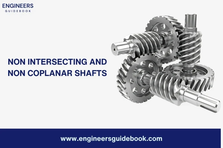
Intersecting and coplanar shaft gears

2. According To Velocity of Gears

  1. Low-Velocity Gears
  2. Medium-Velocity Gears
  3. High-Velocity Gears
Low-Velocity Gears

Low-velocity gears are those gears that operate at a velocity of less than 3 m/s. These gears are designed to handle slower speeds and are commonly used in applications where precise control and reduced wear are important factors.

Medium-Velocity Gears

Medium-velocity gears are gears that operate at a velocity ranging from 3 to 15 m/s. These gears are suitable for applications that require moderate speeds. They offer a balance between power transmission efficiency and wear resistance, making them versatile for various mechanical systems.

High-Velocity Gears

High-velocity gears are gears that operate at a velocity exceeding 15 m/s. These gears are specifically designed to handle high-speed applications. They are engineered to withstand the forces and stresses associated with rapid motion, ensuring reliable performance and durability.

3. According To Type of Gearing

  1. External Gearing
  2. Internal Gearing
  3. Rack and Pinion
External Gearing

In external gearing, the gears of two shafts engage with each other on the outer surface, as illustrated in Figure. The larger gear in this arrangement is known as the spur gear or gear wheel, while the smaller gear is called the pinion. External gearing is commonly used in various mechanical systems to transmit power and motion efficiently.
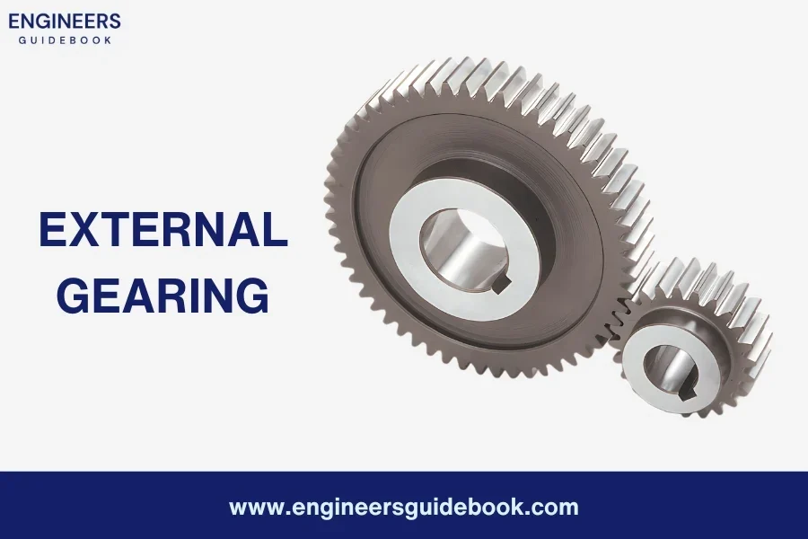
External gearing
Internal Gearing

In internal gearing, the gears of two shafts mesh internally within each other, as depicted in Figure. The larger gear in this configuration is referred to as the annular gear, while the smaller gear is known as the pinion. Internal gearing is employed in applications where compactness and smooth operation are desired, allowing the gears to mesh on the inside of the gear teeth.
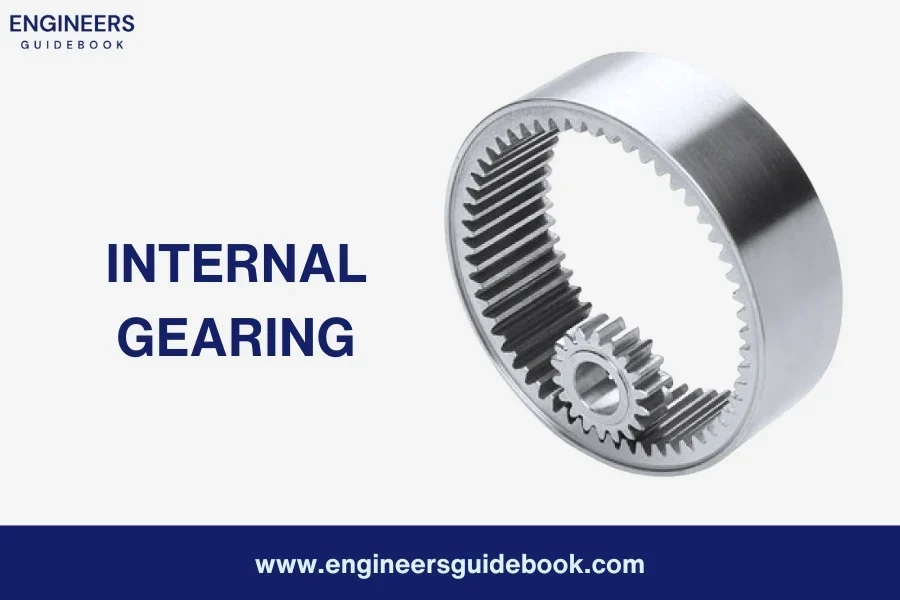
Internal gearing
Rack and Pinion

Sometimes, a combination of external and internal gears is used, resulting in a straight-line gear arrangement known as rack and pinion, as shown in Figure. In this setup, the gear on the shaft meshes externally with a linear gear called the rack, while internally engaging with the circular gear called the pinion. Rack and pinion systems are commonly used to convert rotary motion into linear motion, facilitating precise control and efficient power transmission.
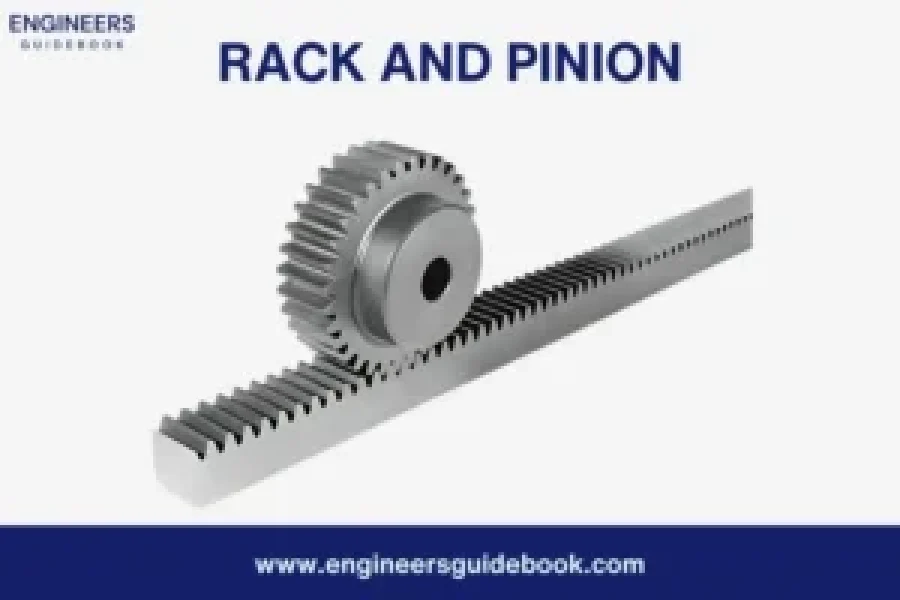
Rack and pinion

Types of Gears

1. Spur Gears

Read More: Spur gears: Types, Advantages, Disadvantages & Applications

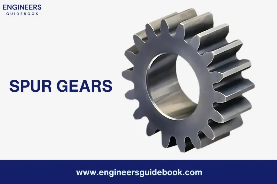
Spur gears are gear wheels with straight teeth that are mounted on parallel shafts. These gears are designed to mesh with each other, transferring rotational motion and torque between the shafts. The teeth of spur gears are evenly spaced and cut straight across the gear’s face.

Advantages of Spur Gears
  1. Simple and compact design
  2. Cost-effective to manufacture
  3. High efficiency in power transmission
  4. Wide range of sizes and ratios available
  5. Easy to maintain and replace
Disadvantages of Spur Gears
  1. Generates high noise levels
  2. Limited to parallel shaft arrangements
  3. Prone to axial thrust and backlash
  4. Requires proper lubrication for smooth operation
  5. May experience increased wear and tear
Applications

Spur gears find applications in various industries and mechanical systems, including:
  • Automotive industry: Spur gears are used in automobile transmissions and engine mechanisms.
  • Robotics: They are utilized in robotic arms, joints, and drive mechanisms.
  • Industrial machinery: Spur gears are employed in conveyor systems, printing machines.
  • Clocks and watches: Spur gears are crucial components in timekeeping mechanisms.
  • Home appliances: They are used in appliances like washing machines, mixers, and blenders.
Spur gears

2. Bevel Gears

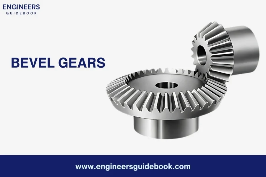
Bevel gears are gear wheels with teeth that are cut on conical surfaces. Unlike spur gears, which have teeth parallel to the axis, bevel gears have teeth that are angled and mesh with each other at the point of intersection. This design allows bevel gears to transmit motion between shafts that are not parallel but intersecting.

Advantages of bevel gears
  1. Efficient power transmission at varying angles
  2. Ability to transmit motion between intersecting shafts
  3. Versatility in handling different speed ratios
  4. Smooth and quiet operation
  5. Widely available in various sizes and configurations
Disadvantages of bevel gears
  1. Complex design and manufacturing process
  2. Higher cost compared to spur gears
  3. Requires proper alignment for optimal performance
  4. Limited load-carrying capacity
  5. Increased complexity for maintenance and repair
Applications

Bevel gears find wide-ranging applications in various industries and mechanical systems, including:
  • Automotive industry: Bevel gears are used in differential systems, where they distribute power between the rear wheels, allowing smooth turns.
  • Marine industry: They are crucial in marine propulsion systems, such as boat sterndrives, enabling efficient power transmission from the engine to the propeller.
  • Power tools: Bevel gears are employed in power saws, drills, and milling machines, delivering controlled and precise movements.
  • Heavy machinery: They are utilized in construction and mining equipment, where they transmit power and motion in challenging working conditions
Bevel gears

3. Helical Gears

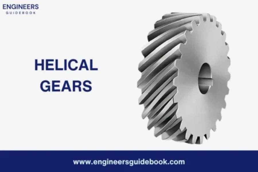
Helical gears are gear wheels with angled teeth that are cut in a helix shape around the gear’s circumference. Unlike spur gears with straight teeth, helical gears have a twisted tooth profile that allows for smoother engagement and quieter operation.

Advantages of Helical gears
  1. Smooth and quiet operation
  2. Increased load-carrying capacity
  3. Higher efficiency due to greater contact area
  4. Improved torque transmission
  5. Better resistance to shock and impact loads
Disadvantages of Helical gears
  1. Higher axial thrust compared to spur gears
  2. More complex design and manufacturing process
  3. Require proper alignment for optimal performance
  4. Slightly lower mechanical efficiency compared to spur gears
  5. Increased cost compared to spur gears
Applications

Helical gears are widely used in various industries and mechanical systems due to their advantages in power transmission. Some notable applications include:
  • Automotive industry: Helical gears are commonly found in automotive transmissions, providing smooth and efficient gear shifting for better vehicle performance.
  • Machinery and equipment: They are utilized in heavy machinery such as industrial mixers, extruders, and crushers, enabling reliable power transmission under high loads.
  • Robotics and automation: Helical gears play a crucial role in robotic arms, CNC machines, and automated systems, delivering precise and synchronized movements.
  • Aerospace industry: They are employed in aircraft engines, gearboxes, and landing systems, providing reliable power transmission in demanding aviation environments.
  • Power generation: Helical gears can be found in wind turbines and power plant equipment, helping to transfer rotational motion from turbines to generators.
Helical gears

4. Double Helical Gears

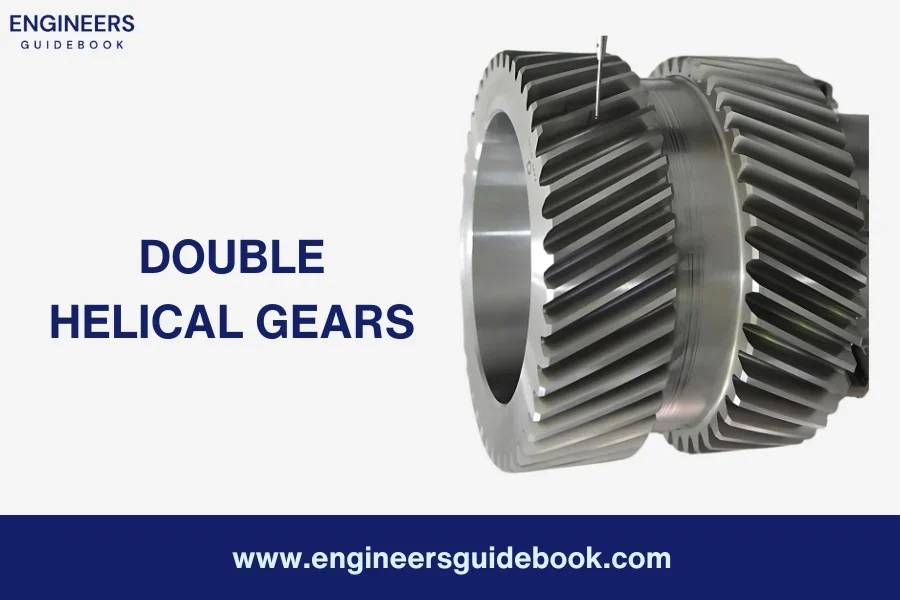
Double helical gears are gear wheels that feature two sets of teeth with a V-shaped groove in the middle, forming a unique herringbone pattern. This design allows for improved load distribution, reduced axial thrust, and enhanced performance compared to traditional helical gears.

Advantages of Double Helical gears
  1. Reduced axial thrust
  2. Improved load distribution
  3. Increased load-carrying capacity
  4. Smoother operation and reduced noise and vibration
  5. Enhanced durability and resistance to wear
Disadvantages of Double Helical gears
  1. More complex design and manufacturing
  2. Higher manufacturing costs
  3. Limited availability of specialized machinery for production
  4. Requires precise alignment during assembly
Applications

Double helical gears find applications in various industries and mechanical systems where precise and reliable power transmission is required. Some notable applications include:
  • Heavy machinery and equipment: Double helical gears are commonly used in large industrial machines such as extruders, crushers, and mills, delivering high torque transmission and improved stability.
  • Oil and gas industry: They are employed in oil drilling equipment, pumps, and compressors, handling the high torque demands and ensuring efficient power transfer.
  • Power generation: Double helical gears can be found in power plant turbines, gearboxes, and generators, providing reliable and smooth operation in electricity generation systems.
  • Marine propulsion: They are utilized in ship propulsion systems, ensuring efficient power transmission from engines to propellers, even under challenging marine conditions.
  • Gearboxes and transmissions: Double helical gears are often used in heavy-duty gearboxes and high-performance automotive transmissions, delivering smooth gear shifting and increased durability.
Double helical gears

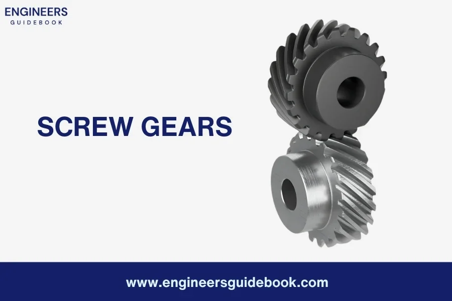
5. Screw Gears

Screw gears, or worm gears, consist of a cylindrical screw-like gear called the worm and a toothed gear called the worm wheel. The worm has a spiral thread that meshes with the teeth of the worm wheel, allowing for efficient power transfer with a high gear ratio.

Advantages of Screw Gears
  1. High gear reduction
  2. Compact design
  3. High torque output
  4. Self locking capability
  5. Precise motion control
Disadvantages of Screw Gears
  1. Lower efficiency compared to other gear types
  2. Limited ability to handle high-speed rotation
  3. Potential for backlash and vibration
  4. Requires proper lubrication for optimal performance
  5. Complex manufacturing process
Applications

Screw gears find extensive applications in various industries and mechanical systems. Some notable applications include:
  • Gearboxes: Screw gears are commonly used in gearboxes of machinery and equipment, providing precise speed reduction and torque multiplication.
  • Conveyor systems: They are utilized in conveyor systems to control the movement of materials, ensuring smooth and accurate transportation.
  • Lifting equipment: Screw gears are employed in lifting mechanisms such as screw jacks and hoists, allowing for controlled vertical movement with high load capacity.
  • Automotive industry: They can be found in automotive steering systems, providing a compact and efficient method for converting rotational motion to linear motion.
  • Robotics: Screw gears are used in robotic arms and joints, offering precise and controlled movement in robotic applications.
Screw gears

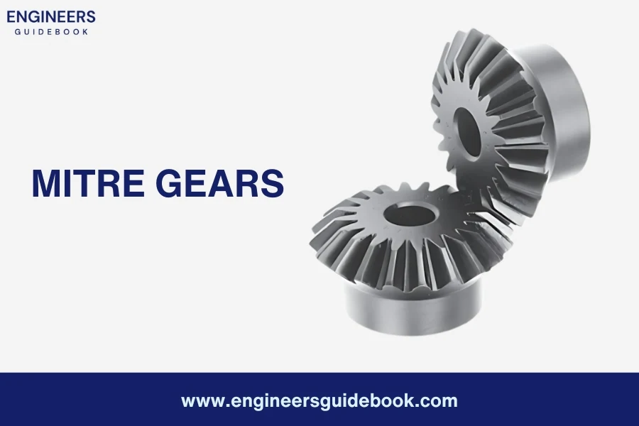
6. Mitre Gears

Mitre gears are a type of gear mechanism with conically shaped teeth designed to mesh at a 90-degree angle. They are used to transfer rotational motion and torque between two intersecting shafts while maintaining a constant speed ratio. Mitre gears are commonly used in applications where a change in shaft direction is required.

Advantages of Miter Gears
  1. Efficient power transmission
  2. Compact and space-saving design
  3. Versatility in changing shaft direction
  4. Smooth and reliable operation
  5. Suitable for intersecting shafts at a 90-degree angle
Disadvantages of Miter Gears
  1. Limited load-carrying capacity
  2. Higher manufacturing complexity compared to straight gears
  3. Increased manufacturing costs
  4. Requires precise alignment for optimal performance
  5. Limited speed ratios compared to other gear types
Applications

Mitre gears find wide applications in various mechanical systems across different industries. Some common applications include:
  • Power transmission: in automotive differentials and drive systems.
  • Robotics and automation: for changing the direction of motion in joints and manipulator arms.
  • Machine tools: such as milling machines and lathes for transmitting motion between intersecting shafts.
  • Printing presses: for transferring power between different sections of the machinery.
  • Hand tools: such as hand drills and electric screwdrivers for changing the direction of rotation.


Mitre gears

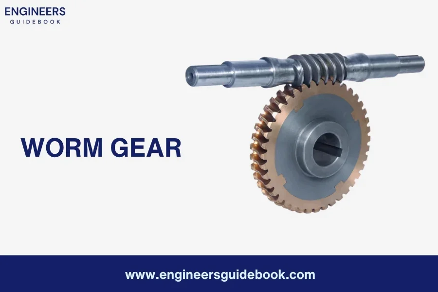
7. Worm Gear

A worm gear consists of a cylindrical gear called a worm and a toothed wheel known as a worm wheel or worm gear. The worm has a helical thread that meshes with the teeth of the worm wheel. This unique configuration allows the worm gear to convert rotational motion between non-intersecting and perpendicular shafts.

Advantages of Worm Gears
  1. High gear reduction ratio
  2. Compact design
  3. Precise motion control
  4. Self-locking capability
  5. High shock load resistance
Disadvantages of worm Gears
  1. Lower efficiency compared to other gear types
  2. Limited speed capabilities
  3. Increased friction and heat generation
  4. Limited applications due to specific requirements
  5. Potential for backlash
Applications

Worm gears find applications in various industries and mechanical systems where precise motion control and high gear reduction are essential. Some common applications include:
  • Automotive industry: Worm gears are used in steering systems to transmit motion from the steering wheel to the wheels, allowing for smooth and controlled steering.
  • Conveyor systems: They are employed in conveyor belts to regulate the movement of materials in industries such as manufacturing, mining, and logistics.
  • Lifts and elevators: Worm gears are used in lifting mechanisms to provide controlled vertical movement in buildings, warehouses, and other structures.
  • Machine tools: They find application in milling machines, lathes, and other machine tools to control the rotational speed and feed rate.
  • Packaging machinery: Worm gears are utilized in packaging equipment for precise control of material handling and filling processes.
Worm gear

8. Internal gears

Internal gears are gear wheels with teeth positioned on the inner surface of the gear rim. Unlike external gears where the teeth are on the outer surface, internal gears have teeth facing inward. They are designed to mesh with external gears, allowing for smooth and efficient power transmission between parallel or concentric shafts.

Advantages of Internal Gears
  1. Compact design
  2. High torque transmission
  3. Smooth and quiet operation
  4. Efficient power transmission
  5. Suitable for compact spaces
Disadvantages of Internal Gears
  1. Complex manufacturing process
  2. Limited gear ratio options
  3. Higher manufacturing costs
  4. Requires precise alignment
  5. More challenging maintenance
Applications

Internal gears find a wide range of applications in various industries and mechanical systems. Some notable applications include:

  • Gearboxes and transmissions: Internal gears are commonly used in automotive transmissions and industrial gearboxes, enabling smooth and reliable power transmission between shafts.
  • Robotics: They are utilized in robotic joints, manipulator arms, and other robotic mechanisms to achieve precise and controlled movement.
  • Machine tools: Internal gears can be found in milling machines, lathes, and other machine tools, contributing to accurate and synchronized operation.
  • Printing presses: They play a crucial role in printing machines, ensuring consistent and precise paper feeding and movement.
  • Wind turbines: Internal gears are employed in wind turbine systems, helping convert wind energy into electrical power efficiently.
Internal gearing

9. External gears

External gears are gear wheels that mesh with each other externally. They consist of two gears, namely the larger gear known as the spur wheel or gear, and the smaller gear called the pinion. The teeth of the gears are located on the outer circumference, allowing them to engage and transmit power.

Advantages of External Gears
  1. Simple and widely used design
  2. Easy to manufacture and assemble
  3. Cost-effective solution
  4. Efficient power transmission
  5. Suitable for various applications
Disadvantages of External Gears
  1. Higher noise and vibration levels
  2. Limited load-carrying capacity
  3. Limited gear ratio options
  4. Requires regular lubrication
  5. Limited flexibility in design
Applications

External gears are utilized in a wide range of applications across various industries. Some notable applications include:

  • Automotive industry: External gears transmit power and control motion in automobile transmissions, engine mechanisms, and steering systems.
  • Industrial machinery: They are employed in conveyor systems, printing machines, power tools, and other industrial equipment to enable power transmission and control rotational motion.
  • Clocks and watches: External gears play a crucial role in clocks and watches’ timekeeping mechanisms, ensuring the accurate movement of hands and precise time measurement.
  • Home appliances: They transfer power and enable the desired motion in appliances such as washing machines, mixers, blenders, and kitchen gadgets.
External gearing

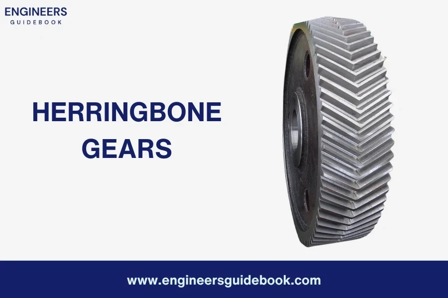
10. Herringbone gears

Herringbone gears are gear wheels that feature a unique double helical design, resembling the letter “V” or the shape of a herringbone fish’s skeleton. The gears have teeth that are cut in a zigzag pattern, with each tooth having a convex and concave side. This design allows for improved load-carrying capacity, reduced noise and vibration, and enhanced efficiency in power transmission.

Advantages of Herringbone gears
  1. High load-carrying capacity
  2. Balanced forces and reduced vibration
  3. Smoother and quieter operation
  4. Efficient power transmission
  5. Suitable for high-speed applications
Disadvantages of Herringbone gears
  1. Complex and costly manufacturing process
  2. Limited availability of specialized manufacturing equipment
  3. Requires precise alignment during assembly
  4. Higher production costs
Applications

Herringbone gears find a wide range of applications in various industries and mechanical systems that require high-performance power transmission and motion control. Some notable applications include:
  • Heavy machinery: Herringbone gears are commonly used in heavy-duty machinery, such as turbines, compressors, and gearboxes, due to their ability to handle large loads and provide smooth power transmission.
  • Oil and gas industry: They are utilized in drilling equipment, pumps, and refineries, ensuring reliable and efficient power transmission in harsh environments.
  • Power generation: Herringbone gears are employed in wind turbines, hydroelectric generators, and steam turbines, delivering high torque and efficient energy conversion.
  • Marine propulsion: They can be found in ship propulsion systems, ensuring smooth and reliable power transmission in marine vessels.
  • Paper and printing industry: Herringbone gears are used in printing presses, paper mills, and converting machines, providing precise motion control and high-speed operation.
Herringbone gears

11. Hypoid Gears

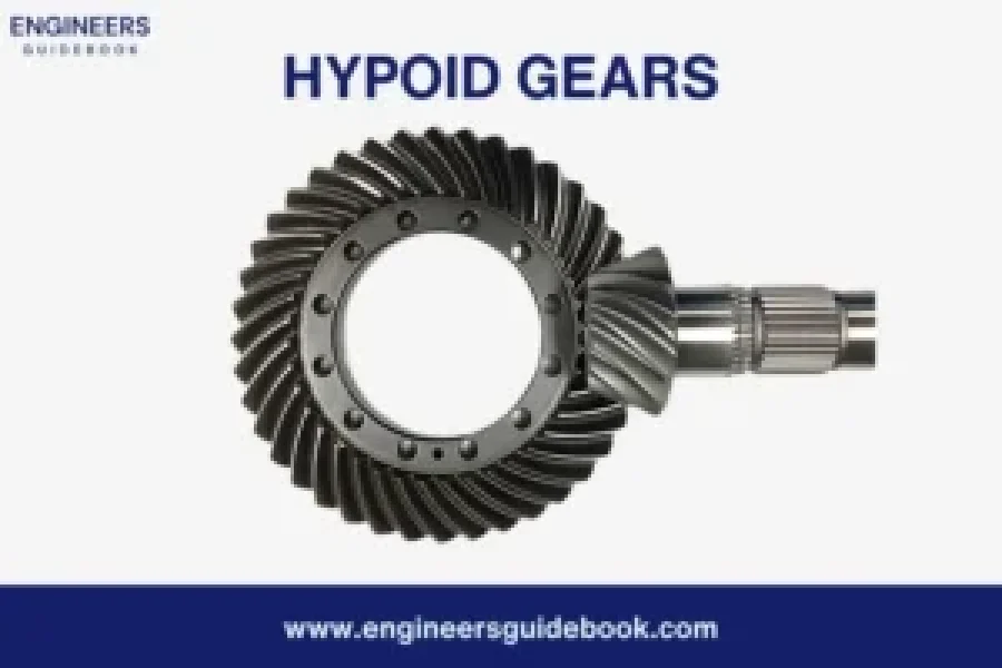
Hypoid gears are gear wheels that have offset axes and non-intersecting shafts. Unlike bevel gears, which have intersecting axes, hypoid gears have a slight offset between the axes of the driving and driven gears. This unique design allows for efficient power transmission between non-parallel shafts, while also providing compactness and versatility.

Advantages of Hypoid gears
  1. Efficient power transmission between
  2. non-parallel shafts
  3. Compact and versatile design
  4. Ability to handle high torque and heavy loads
  5. Smooth and reliable motion control
Disadvantages of Hypoid gears
  1. Complex design and manufacturing process
  2. Requires proper lubrication for optimal performance
  3. Limited availability of specialized manufacturing equipment
  4. Requires precise alignment during assembly
Applications

Hypoid gears find wide applications in various industries and mechanical systems that require efficient and reliable power transmission. Some notable applications include:
  • Automotive industry: Hypoid gears are commonly used in rear-wheel drive vehicles, especially in the differential systems. They enable smooth power transfer from the engine to the wheels, providing traction and torque distribution.
  • Power tools and machinery: They are utilized in power saws, drills, and other heavy-duty machinery, delivering high torque and efficient motion control.
  • Robotics and automation: Hypoid gears can be found in robotic arms, joints, and industrial automation systems, ensuring precise and synchronized movement.
  • Construction and mining equipment: They are employed in heavy machinery such as excavators and bulldozers, allowing for reliable power transmission in rugged environments.
  • Wind turbines: Hypoid gears are used in wind turbine systems to convert the rotational motion of the blades into electricity, providing clean and renewable energy.
Hypoid gears

12. Crown Gears

Crown gears, also known as bevel gears, are a type of gear where the teeth are cut on a conical surface. These gears are designed to transmit motion between shafts that are not parallel. Typically, they connect shafts that are at right angles (90 degrees) to each other.

Advantages of crown gears
  1. Transmitting motion between non-parallel shafts
  2. High efficiency
  3. Smooth operation
  4. Versatility
  5. High load capacity
Disadvantages of crown gears
  1. Limited tooth contact
  2. Increased wear
  3. Complex manufacturing process
  4. Alignment sensitivity
  5. Limited speed capabilities
Applications
  • Marine Propulsion Systems: Crown gears are used in marine propulsion systems to transfer power from the engine to the propeller shafts, allowing for efficient direction changes.

  • Winches: In winching systems, crown gears help in transferring motion between non-parallel shafts, facilitating the lifting and pulling of heavy loads.

  • Automotive Differentials: Crown gears are essential components in automotive differentials, enabling wheels to rotate at different speeds while turning.

  • Aerospace Control Systems: These gears are used in aerospace control systems to change the direction of motion and manage the precise movement of control surfaces.

  • Industrial Machinery: Crown gears are widely used in various types of industrial machinery, such as conveyors and material handling equipment, where direction changes are necessary.
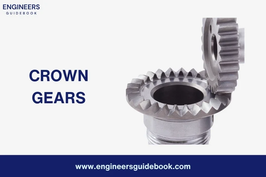
Crown gears

13. Non-circular gears

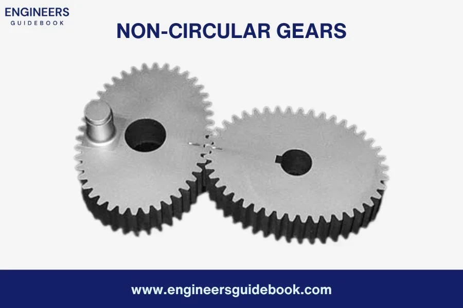
Non-circular gears are a type of gear whose shape is not round. Unlike traditional circular gears, these gears have varying radii and are designed to achieve specific motion profiles. They work by meshing together and transmitting torque and rotational motion in a way that results in non-uniform speed and torque outputs. This unique capability allows them to meet specific mechanical requirements that circular gears cannot.
Advantages of Non-circular gears
  1. Customizable Motion Profiles
  2. Space Efficiency
  3. Improved Performance
  4. Versatility
  5. Reduced Wear and Tear
Disadvantages of Non-circular gears
  1. Complex Design and Manufacturing
  2. Limited Standardization
  3. Higher Initial Costs
  4. Specialized Maintenance
  5. Precision Requirements
Applications
  • Packaging Machinery: Non-circular gears are used in packaging machines to create specific motion profiles that handle delicate materials efficiently and effectively.
  • Cam Mechanisms: In cam mechanisms, they provide precise control over the motion of followers, enhancing the performance and reliability of the system.
  • Printing Presses: They are used to control the paper feed mechanisms, ensuring consistent speed and tension throughout the printing process.
  • Textile Machines: In textile manufacturing, non-circular gears help manage the complex motion needed for weaving and knitting machines.
  • Robotics: These gears are employed in robotics to create complex and precise movements, improving the functionality and efficiency of robotic arms and other automated systems.
Non-circular gears

14. Harmonic Drive Gears

Harmonic drive gears, also known as strain wave gears, are a type of mechanical gear system that delivers high precision, excellent torque capacity, and zero backlash. These gears consist of three main components:
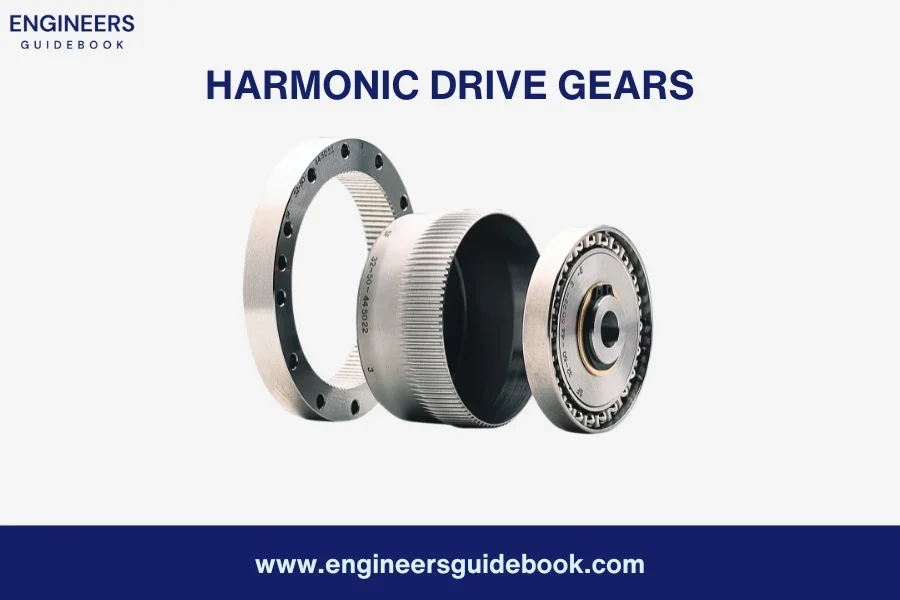
  • Circular Spline
  • Flex spline
  • Wave Generator
Advantages of Non-circular gears
  1. High Precision
  2. Zero Backlash
  3. Compact Size
  4. High Torque Capacity
  5. Durability
Disadvantages of Non-circular gears
  1. Complex Manufacturing
  2. Limited Flexibility
  3. Sensitivity to Overloads
  4. Higher Cost
Applications
  • Robotics: Utilized in robotic arms and joints for precise movement and control.
  • Aerospace: Used in flight control systems and satellite positioning due to their reliability and accuracy.
  • Medical Devices: Implemented in surgical robots and diagnostic equipment for precision operations.
  • Automation: Employed in automated machinery and assembly lines for efficient and accurate performance.
  • Optics: Found in telescopes and camera systems where precise positioning is crucial.
Harmonic drive gears

Future Trends in Gear Technology

Gears have been essential components in machinery for centuries. From clocks to cars, gears help transfer motion and power efficiently. As technology advances, gear technology also evolves. Here’s a look at the future trends and advancements in gear technology that are set to shape industries.

1. Additive Manufacturing and 3D Printing

3D printing allows for the creation of highly precise and customized gears. This technology enables manufacturers to produce complex shapes that were previously impossible or too costly with traditional methods.

With 3D printing, prototypes can be produced quickly and tested for functionality. This accelerates the development process and allows for faster iteration and improvement of gear designs.

2. Improved Lubrication Techniques

Nanotechnology is being used to develop lubricants that significantly reduce friction and wear. These advanced lubricants can enhance the efficiency and lifespan of gears by providing better protection against heat and pressure.

Materials that incorporate self-lubricating properties are being developed. These gears can reduce the need for regular maintenance and improve the reliability of machinery.

3. Enhanced Gear Design Software

Advanced software tools now allow for detailed simulation and analysis of gear performance. Engineers can predict how gears will behave under different conditions and optimize their designs accordingly.

Artificial intelligence and machine learning are being integrated into gear design software. These technologies can analyze vast amounts of data to identify patterns and suggest improvements, leading to more efficient and innovative gear designs.

4. Energy Efficiency and Sustainability

There is a growing focus on using eco-friendly materials in gear manufacturing. These materials reduce the environmental impact and align with the global push towards sustainability.

Engineers are developing gears that operate more efficiently, reducing energy consumption. This is particularly important in industries like automotive and industrial machinery, where energy efficiency is crucial for cost savings and environmental protection.

FAQ'S

What are the 8 types of gears?

Gears are mechanical components used to transmit motion and torque between machine parts. There are several types of gears, each designed for specific applications and mechanical advantages. The eight common types of gears are:

  • Spur Gears
  • Helical Gears
  • Bevel Gears
  • Worm Gears
  • Rack and Pinion
  • Planetary Gears
  • Herringbone Gears
  • Hypoid Gears

Gears are wheels that have projections (called teeth) as shown in fig are provided on the periphery of wheel A which will fit into the corresponding recesses on the periphery of wheel B. A friction wheel with teeth cut on it is known as gear or toothed wheel.

Classification of gears :
  • According To Position of Axes of The Shafts
  • According To Peripheral Velocity Of The Gears
  • According To Type of Gearing

The most common type of gear is the spur gear. Spur gears are widely used due to their simple design, ease of manufacture, and efficiency in transmitting motion and torque between parallel shafts. They are commonly found in various applications, including clocks, washing machines, and industrial machinery.

There are 2 basic functions of gears:

  • Gears are used to transmit the exact velocity ratio.
  • Gears are used to transmit power between the shafts.

By altering the size and number of teeth on the gears, engineers can control the speed and direction of the equipment.

There are 2 basic functions of gears:

  • Gears are used to transmit the exact velocity ratio.
  • Gears are used to transmit power between the shafts.

By altering the size and number of teeth on the gears, engineers can control the speed and direction of the equipment.

Spur gears are gear wheels with straight teeth that are mounted on parallel shafts. These gears are designed to mesh with each other, transferring rotational motion and torque between the shafts. The teeth of spur gears are evenly spaced and cut straight across the gear’s face.
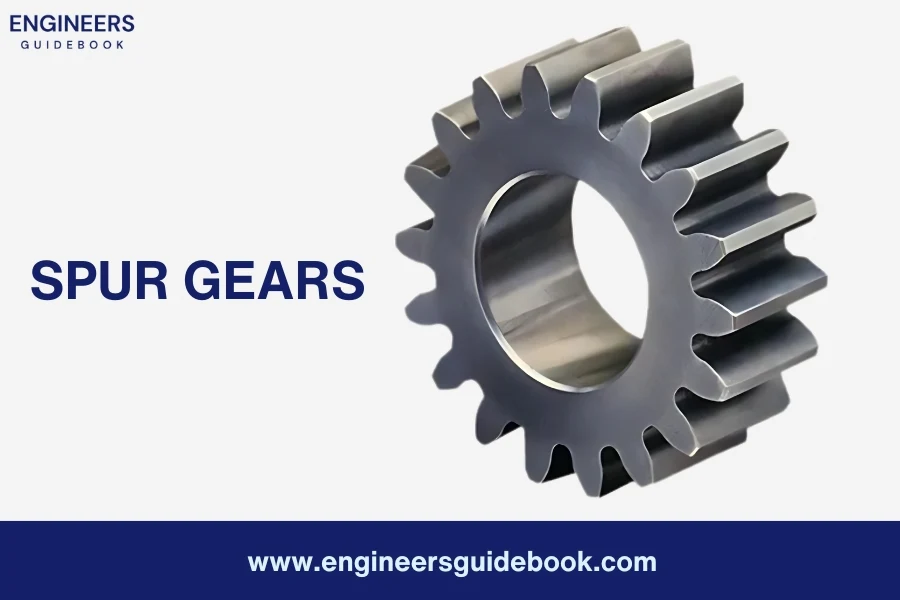
Spur gears

Low-Velocity Gears

Low-velocity gears are those gears that operate at a velocity of less than 3 m/s. These gears are designed to handle slower speeds and are commonly used in applications where precise control and reduced wear are important factors.

Medium-Velocity Gears

Medium-velocity gears are gears that operate at a velocity ranging from 3 to 15 m/s. These gears are suitable for applications that require moderate speeds. 

High-Velocity Gears

High-velocity gears are gears that operate at a velocity exceeding 15 m/s. These gears are specifically designed to handle high-speed applications.

Sometimes, a combination of external and internal gears is used, resulting in a straight-line gear arrangement known as rack and pinion, as shown in Figure. In this setup, the gear on the shaft meshes externally with a linear gear called the rack, while internally engaging with the circular gear called the pinion. Rack and pinion systems are commonly used to convert rotary motion into linear motion, facilitating precise control and efficient power transmission.
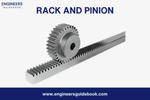
Rack and pinion

Helical gears are gear wheels with angled teeth that are cut in a helix shape around the gear’s circumference. Unlike spur gears with straight teeth, helical gears have a twisted tooth profile that allows for smoother engagement and quieter operation.
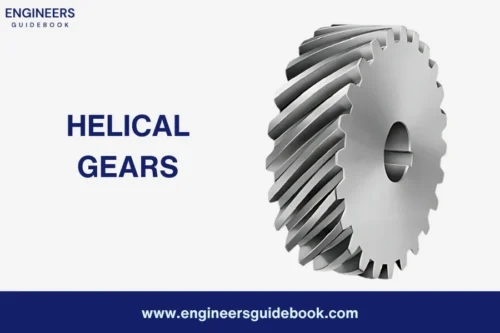
Helical gears

Gear are mostly used for :

  1. Transmission of Power: Transfer power between machine parts.
  2. Speed Reduction: Decrease rotational speed while increasing torque.
  3. Direction Change: Alter the direction of rotational motion.
  4. Synchronization: Coordinate the rotation of multiple shafts.
  5. Mechanical Advantage: Increase force or torque applied to a load.

Gears are mostly used in :

  1. Automobiles: Used in the transmission system to change speed and torque.
  2. Watches: Maintain accurate time by regulating the movement of hands.
  3. Bicycles: Change pedaling speed and effort through gear shifting.
  4. Industrial Machinery: Operate heavy equipment by transferring power efficiently.
  5. Aerospace: Control and maneuver aircraft systems and components.

Herringbone gears are gear wheels that feature a unique double helical design, resembling the letter “V” or the shape of a herringbone fish’s skeleton. The gears have teeth that are cut in a zigzag pattern, with each tooth having a convex and concave side. This design allows for improved load-carrying capacity, reduced noise and vibration, and enhanced efficiency in power transmission.
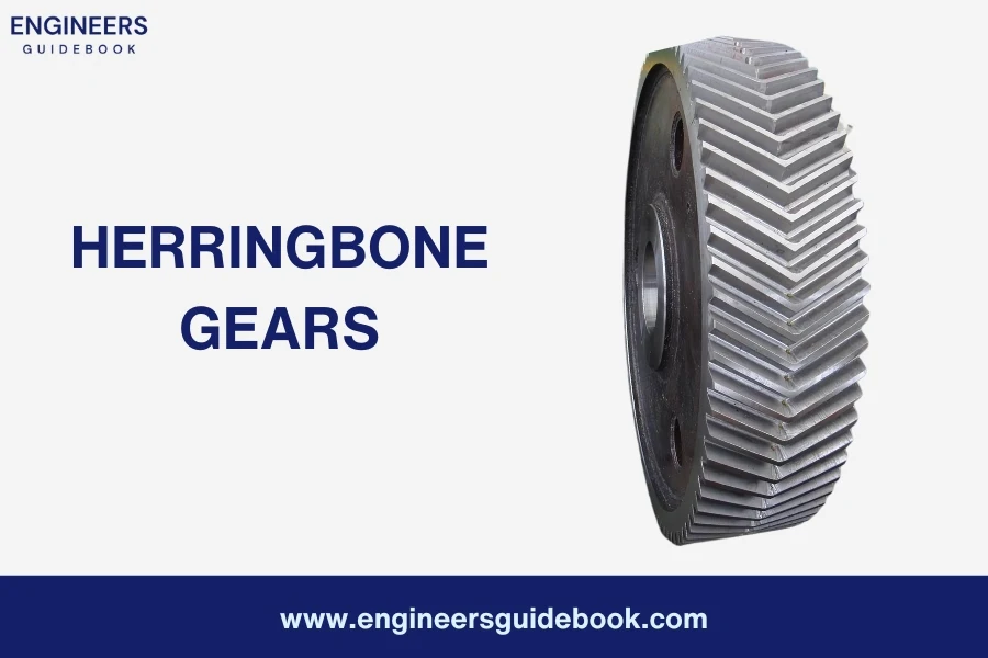
                              Herringbone gears

Hypoid gears are gear wheels that have offset axes and non-intersecting shafts. Unlike bevel gears, which have intersecting axes, hypoid gears have a slight offset between the axes of the driving and driven gears. This unique design allows for efficient power transmission between non-parallel shafts, while also providing compactness and versatility.
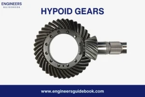
                                  Hypoid gears

Mitre gears are a type of gear mechanism with conically shaped teeth designed to mesh at a 90-degree angle. They are used to transfer rotational motion and torque between two intersecting shafts while maintaining a constant speed ratio. Mitre gears are commonly used in applications where a change in shaft direction is required.
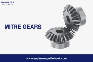
                              Mitre gears 

Author

Muhammad ali
Muhammad Ali

Muhammad Ali holds a PhD in Mechanical Engineering from MIT and is a writing specialist. His groundbreaking research on sustainable energy systems and renewable energy integration has earned him numerous accolades. His passion for innovation and education shines through in his insightful and inspiring writings.

Facebook
Twitter
LinkedIn
WhatsApp

Sign up for our Newsletter