1. Mechanical Seals Overview
Mechanical seals are critical sealing devices used to control fluid leakage where a rotating shaft passes through a stationary housing. They are widely used in pumps, compressors, mixers, agitators, and many other rotating machines. Their purpose is simple, but their engineering is highly refined.
A mechanical seal creates a controlled sealing interface between two precision surfaces. One surface rotates with the shaft, while the other remains stationary. Together, they prevent process fluid from escaping while allowing the shaft to rotate smoothly.
1.1 Mechanical Seals in Simple Terms
A mechanical seal is a device that stops liquid or gas from leaking out of rotating equipment. In most cases, it is installed around the shaft of a pump or machine. The shaft must rotate, but the fluid inside the equipment must remain contained.
This is not easy. A rotating shaft always creates a potential leakage path. Mechanical seals solve this problem by using carefully machined faces that press against each other with controlled force.
The seal does not work by brute compression alone. It works through a delicate tribological relationship between contact pressure, surface finish, lubrication, and heat dissipation.

2. Core Function of Mechanical Seals
The core function of a mechanical seal is to control leakage between rotating and stationary parts. However, its role is broader than simply stopping fluid escape. It also supports system pressure, prevents ingress of external contaminants, and protects equipment from avoidable deterioration.
A seal is a small component with a large operational impact. When it performs well, the equipment runs quietly and efficiently. When it fails, the entire process can be interrupted.
2.1 Leakage Control
Leakage control is the primary purpose of a mechanical seal. The seal faces create a narrow interface where fluid escape is restricted to an extremely small amount.
In many applications, this leakage is almost invisible. A microscopic lubricating film may exist between the faces, but excessive fluid discharge is prevented. This controlled sealing action is what separates mechanical seals from crude compression-based sealing methods.
Leakage control is especially important when handling hazardous, expensive, corrosive, or volatile fluids. It protects people, process material, and the surrounding environment.
2.2 Shaft Sealing
The shaft is one of the most common leakage paths in rotating equipment. Since the shaft must pass through the pump casing or machine housing, a clearance is necessary. That clearance becomes a natural escape route for fluid.
A mechanical seal closes this route without stopping shaft rotation. It seals around the shaft while accommodating movement, vibration, pressure variation, and thermal expansion.
This function demands precision. The seal must remain tight, but it must not grip the shaft so aggressively that it generates excessive friction or wear.
2.3 Pressure Retention
Mechanical seals help retain pressure inside the equipment. In a pump, pressure is required to move fluid from one point to another. If the seal cannot hold pressure, system performance suffers.
Pressure retention also supports process stability. Loss of pressure may reduce flow rate, disturb operating conditions, or cause cavitation-like symptoms in nearby equipment.
High-pressure services require special seal designs. Balanced seals, hard face materials, and proper flush systems are often used to control hydraulic loading and prevent overheating.
2.4 Contamination Prevention
Mechanical seals do not only keep process fluid inside. They also help keep external contaminants outside.
Dust, moisture, dirt, and atmospheric oxygen can enter equipment through poor sealing points. In sensitive processes, such contamination can degrade product quality or damage internal parts.
This is especially important in pharmaceutical, food, beverage, and high-purity chemical applications. A reliable seal helps preserve cleanliness, sterility, and product consistency.
2.5 Equipment Protection
A mechanical seal protects the equipment by reducing leakage-related damage. Escaping fluid can corrode baseplates, damage bearings, attack paint, contaminate lubricants, and create unsafe floor conditions.
Seal failure can also trigger secondary failures. A leaking pump may run dry. A contaminated bearing housing may overheat. A corrosive leak may destroy nearby instrumentation.
By maintaining fluid containment, the mechanical seal contributes directly to machine reliability and lifecycle cost reduction.

3. Main Parts of a Mechanical Seal
A mechanical seal is made up of several engineered components working together. Each part has a specific role in sealing, loading, alignment, transmission of torque, or secondary containment.
Although designs vary, most mechanical seals include rotating and stationary faces, secondary seals, springs, a gland plate, a sleeve, retainers, and a drive mechanism. The performance of the entire seal depends on the correct interaction of these parts.
3.1 Rotating Face
The rotating face is attached to the shaft or sleeve and rotates with it. It is one of the two primary sealing faces.
This face must be flat, smooth, and resistant to wear. Even tiny distortions can create leakage paths. For this reason, seal faces are manufactured with high precision and often lapped to achieve excellent flatness.
Rotating faces may be made from carbon, silicon carbide, tungsten carbide, ceramic, or other specialized materials. The selection depends on fluid type, pressure, speed, and temperature.
3.2 Stationary Face
The stationary face remains fixed in the seal gland or housing. It presses against the rotating face to form the primary sealing interface.
Like the rotating face, it must maintain excellent flatness and surface finish. A stable stationary face helps maintain consistent sealing pressure and prevents irregular wear patterns.
The material pairing between rotating and stationary faces is extremely important. A hard-on-hard combination may be used for abrasive fluids, while carbon against a harder material is common in cleaner services.
3.3 Secondary Seals
Secondary seals prevent leakage around the mechanical seal components rather than between the main seal faces. These include O-rings, V-rings, wedges, gaskets, and bellows.
Their job is to seal gaps between the shaft sleeve, gland plate, stationary seat, and other hardware. They also allow limited axial movement where required.
Elastomer compatibility is critical. An O-ring that swells, hardens, shrinks, or cracks can cause premature failure even if the seal faces remain in good condition.
3.4 Springs and Loading Elements
Springs provide the closing force that keeps the seal faces together. Without spring force, the faces could separate during startup, shutdown, or pressure fluctuation.
The spring system may use a single coil spring, multiple small springs, wave springs, metal bellows, or elastomeric elements. Each design has advantages depending on service conditions.
Springs must remain clean and free-moving. In dirty or crystallizing fluids, springs can clog, corrode, or lose elasticity, causing erratic face loading.
3.5 Gland Plate
The gland plate holds the stationary components of the seal and connects the seal assembly to the equipment casing. It provides structural support and alignment.
It may also include ports for flushing, quenching, venting, draining, or barrier fluid circulation. These ports are essential in more advanced sealing systems.
A poorly fitted gland plate can cause face misalignment. Even a high-quality seal may fail quickly if the gland is distorted or incorrectly tightened.
3.6 Sleeve and Retainer
The sleeve fits over the shaft and provides a clean, controlled surface for the seal assembly. It protects the actual shaft from wear, corrosion, and fretting.
Retainers hold seal parts in position and help transmit movement or loading forces. In cartridge seals, these components are already preassembled and set by the manufacturer.
A good sleeve reduces maintenance cost because it can be replaced more easily than a damaged shaft. This is especially valuable in expensive pumps and critical rotating assets.
3.7 Drive Mechanism
The drive mechanism transfers rotational motion from the shaft to the rotating seal face. This may be done through set screws, drive pins, lugs, collars, or keys.
The drive system must be secure but not destructive. Excessive tightening can damage the shaft sleeve, while weak engagement can allow slippage.
If the rotating face does not turn properly with the shaft, the seal may chatter, overheat, or fail catastrophically. Reliable torque transmission is therefore indispensable.

4. How Mechanical Seals Work
Mechanical seals work by pressing two precision faces together while allowing a controlled lubricating film between them. This creates a dynamic sealing interface.
The principle appears simple, but the physics is subtle. The seal must control leakage, reduce friction, tolerate pressure, manage heat, and survive mechanical movement.
4.1 Face Contact Principle
The heart of a mechanical seal is the contact between the rotating and stationary faces. These faces are pressed together by springs and hydraulic pressure.
When the equipment starts, the rotating face moves against the stationary face. The interface must remain stable. If contact is too light, leakage occurs. If contact is too heavy, friction and heat increase.
This balance is the central discipline of seal design. The seal faces must touch, but not destructively.
4.2 Thin Fluid Film
A very thin fluid film usually exists between the seal faces. This film lubricates the faces and reduces direct surface damage.
The film may be only microscopic, but it is vital. It prevents galling, lowers friction, and helps remove heat from the interface.
If the film disappears, the seal can run dry. Dry running generates severe heat and may crack carbon faces, blister surfaces, or destroy elastomers.
4.3 Spring Force and Hydraulic Force
Mechanical seals rely on both spring force and hydraulic force. Springs provide initial closing pressure, especially when the equipment is idle or starting.
Hydraulic force comes from the process fluid pressure acting on the seal geometry. Depending on the design, this force may increase or reduce face loading.
Balanced seals are designed to reduce excessive hydraulic closing force. This allows them to handle higher pressures with less friction and heat.
4.4 Heat Generation and Dissipation
Heat is generated at the seal faces due to friction and fluid shear. If heat is not removed, the seal temperature rises rapidly.
Excessive heat damages elastomers, distorts faces, vaporizes fluid film, and accelerates wear. In severe cases, it can cause thermal cracking or face blistering.
Heat dissipation occurs through the process fluid, flush fluid, gland hardware, and surrounding equipment. Proper cooling and lubrication are essential in demanding services.
4.5 Balance Between Sealing and Lubrication
A mechanical seal must seal tightly while still allowing enough lubrication to protect the faces. This is a paradoxical requirement.
Too much leakage is unacceptable. Too little fluid film is dangerous. The best seal performance occurs when the interface maintains a stable, controlled microfilm.
This balance depends on material selection, face geometry, pressure, temperature, speed, and fluid characteristics. It is not accidental. It is engineered.

5. Major Types of Mechanical Seals
Mechanical seals are available in many types because industrial services vary widely. A seal used for clean water may not be suitable for acid, solvent, slurry, steam condensate, or high-pressure hydrocarbons.
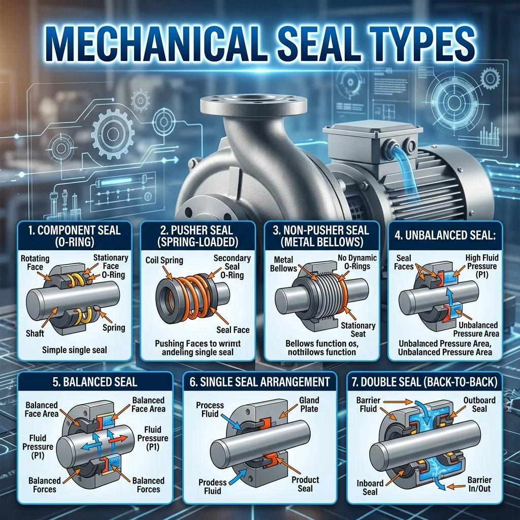
The main classifications include pusher, non-pusher, balanced, unbalanced, single, double, cartridge, and component seals. Each type solves a different sealing challenge.
5.1 Pusher Seals
Pusher seals use a dynamic secondary seal, usually an O-ring, that moves axially along the shaft or sleeve. This movement allows the seal faces to compensate for wear.
They are common, economical, and versatile. However, the sliding O-ring can become stuck due to corrosion, crystallization, or product buildup.
Pusher seals are suitable for many general-purpose services, especially where the fluid is clean and compatible with the elastomer.
5.2 Non Pusher Seals
Non-pusher seals do not rely on a sliding secondary seal to maintain face contact. Instead, they often use a bellows element that flexes.
This design is useful where O-ring hang-up is a concern. It performs well in services involving high temperature, corrosive fluids, or crystallizing products.
Metal bellows and elastomer bellows are common examples. The choice depends on temperature range, chemical exposure, and equipment duty.
5.3 Balanced Seals
Balanced seals reduce the hydraulic force acting on the seal faces. This helps control heat and wear under higher pressure conditions.
They are commonly used when process pressure is too high for an unbalanced design. They are also beneficial when fluid lubricity is poor.
A balanced seal usually has a longer service life in demanding applications. Its geometry distributes pressure more efficiently across the sealing interface.
5.4 Unbalanced Seals
Unbalanced seals have a simpler design and allow more hydraulic force to act on the seal faces. This increases closing force.
They are often used in low-pressure services where the extra loading does not create excessive heat or wear. Their simplicity makes them economical and easy to apply.
However, they are not ideal for high-pressure or poor-lubrication fluids. Excessive face loading can shorten seal life significantly.
5.5 Single Mechanical Seals
A single mechanical seal has one set of sealing faces. It is the most common arrangement in general industrial pumps.
Single seals are suitable for clean, non-hazardous, and moderately demanding fluids. They are simple, cost-effective, and relatively easy to maintain.
Their limitation is containment. If the seal leaks, the process fluid may escape directly to atmosphere.
5.6 Double Mechanical Seals
Double mechanical seals use two sets of seal faces. They provide an additional layer of containment and can be arranged in different configurations.
They are used for toxic, flammable, abrasive, expensive, or environmentally sensitive fluids. A barrier or buffer fluid is usually applied between the two seals.
Double seals provide better safety and reliability in critical services. They are more complex, but their protection is often worth the additional cost.
5.7 Cartridge Mechanical Seals
Cartridge seals are preassembled units that include the seal faces, gland, sleeve, and setting devices. They are designed to be installed as one complete assembly.
This reduces installation errors and saves maintenance time. The seal face loading and internal alignment are already set by the manufacturer.
Cartridge seals are widely preferred in modern plants because they improve reliability and simplify maintenance practices.
5.8 Component Mechanical Seals
Component seals are supplied as separate parts and assembled on the equipment during installation. They require more skill and care than cartridge seals.
They are usually less expensive initially, but incorrect installation can cause early failure. Proper measurement, alignment, and cleanliness are essential.
Component seals remain common in small pumps, standard services, and cost-sensitive applications.

6. Single Mechanical Seals
Single mechanical seals are the most widely used seal arrangement in industrial equipment. They consist of one primary sealing interface between a rotating and a stationary face.
Their simplicity makes them attractive. Yet their performance still depends on correct selection, installation, and operating conditions.
6.1 Basic Design
A single mechanical seal has one set of faces, one spring system, secondary seals, and supporting hardware. The rotating part moves with the shaft, while the stationary part is held in the gland.
The seal prevents process fluid from escaping along the shaft. In many designs, the process fluid itself lubricates and cools the seal faces.
This design is compact and efficient. It is often the first choice when the fluid is clean, non-toxic, and not highly volatile.
6.2 Key Advantages
The main advantage of a single mechanical seal is simplicity. Fewer components mean lower cost, easier installation, and straightforward maintenance.
Single seals also occupy less space than double seals. This makes them suitable for compact equipment and standard pump designs.
They provide better leakage control than gland packing and usually require less routine adjustment.

7. Double Mechanical Seals
Double mechanical seals are used when one seal is not enough. They provide two sealing interfaces and create a protected zone between them.
This arrangement is preferred for critical, hazardous, or difficult fluids. It improves safety and allows better control of seal face lubrication and cooling.
7.1 Back to Back Arrangement
In a back-to-back arrangement, the two sets of seal faces are positioned in opposite directions. Barrier fluid is maintained at a pressure higher than the process fluid.
This ensures that if leakage occurs, barrier fluid enters the process rather than process fluid escaping to the atmosphere. It is a strong containment method.
Back-to-back seals are often used for hazardous, toxic, or flammable fluids where atmospheric leakage cannot be tolerated.
7.2 Face to Face Arrangement
In a face-to-face arrangement, the two rotating faces are oriented toward each other. This configuration is compact and can accommodate certain equipment designs.
The barrier or buffer fluid flows between the seals to provide lubrication and heat removal. It also helps stabilize the seal environment.
Face-to-face seals can be useful where space is limited, but their selection must consider pressure direction and operating behavior.

8. Cartridge Mechanical Seals
Cartridge mechanical seals are complete preassembled sealing units. They are designed to simplify installation and reduce human error.
In many modern maintenance programs, cartridge seals are preferred because they provide consistency. They also reduce dependence on field assembly skill.
8.1 Pre Assembled Design
A cartridge seal includes the seal faces, sleeve, gland plate, secondary seals, springs, and setting clips in one assembly. The internal dimensions are preset.
This design removes much of the guesswork from installation. The technician does not need to individually position every component.
Preassembled construction also protects delicate seal faces during handling. It creates a more controlled installation process.
8.2 Easy Installation
Cartridge seals are easier to install than component seals. The unit slides onto the shaft or sleeve and is bolted to the equipment.
Setting clips maintain the correct working length until the seal is secured. After installation, the clips are removed before operation.
This simplicity reduces maintenance time. It is especially valuable during shutdowns, where every hour matters.

9. Component Mechanical Seals
Component mechanical seals are supplied as individual parts. These parts are assembled directly on the shaft or sleeve during installation.
They are traditional, economical, and still widely used. However, they require careful handling and skilled installation.
9.1 Individual Part Assembly
In a component seal, each element is installed separately. The technician must position the stationary seat, rotating face, springs, O-rings, retainers, and other parts correctly.
The working length must be set manually. This dimension determines the correct spring compression and face loading.
A small error can cause leakage, overheating, or rapid wear. Accuracy is essential.
9.2 Cost Benefits
Component seals usually have a lower initial purchase cost than cartridge seals. This makes them attractive for standard equipment and low-risk services.
They are also useful where equipment is simple and maintenance staff are experienced with the seal design.
However, lower purchase cost does not always mean lower total cost. Repeated failures, downtime, and installation errors can quickly erase the savings.
9.3 Installation Skill Requirements
Component seals require more installation skill than cartridge seals. The technician must understand seal orientation, compression length, face handling, and secondary seal placement.
Cleanliness is critical. A fingerprint, dust particle, or small scratch on the face can create leakage.
Proper training is important. Component seals reward skill but punish carelessness.
9.4 Alignment Challenges
Alignment is more challenging with component seals because the assembly depends heavily on field accuracy. Shaft runout, sleeve damage, and gland misalignment can all affect performance.
Uneven tightening of gland bolts may distort the stationary face. Incorrect axial setting may overload or underload the seal faces.
These problems are often invisible during installation but become obvious after startup through leakage, heat, or noise.
9.5 Suitable Applications
Component seals are suitable for small pumps, clean liquids, low-pressure services, and applications where cost control is important.
They are also useful when equipment design does not easily accept cartridge seals. Some older pumps are built around component seal arrangements.
When installed correctly, component seals can perform reliably. Their success depends on workmanship, operating conditions, and proper material selection.

10. Balanced and Unbalanced Seals
Balanced and unbalanced seals differ in how process pressure affects seal face loading. This difference has a major influence on heat generation, wear, and pressure capability.
The choice between them depends mainly on pressure, fluid lubricity, vapor pressure, temperature, and service severity.
10.1 Balanced Seal Design
A balanced seal is designed to reduce the hydraulic closing force acting on the seal faces. This is achieved through specific seal geometry.
By lowering face load, the seal reduces friction and heat. This improves performance at higher pressures.
Balanced seals are especially useful for volatile fluids, poor-lubricating fluids, and applications where heat generation must be minimized.
10.2 Unbalanced Seal Design
An unbalanced seal allows more process pressure to act as closing force on the seal faces. This makes the design simple and robust for low-pressure duties.
The stronger closing force can help prevent leakage in mild services. However, it also increases friction.
At higher pressures, this extra loading can become harmful. It may cause rapid face wear, thermal stress, and shortened seal life.

11. Pusher and Non Pusher Seals
Pusher and non-pusher seals differ in how they compensate for seal face wear and axial movement. This difference affects reliability in dirty, hot, corrosive, or crystallizing services.
The distinction is especially important when choosing seals for chemicals, slurries, high-temperature liquids, and fluids that leave deposits.
11.1 Pusher Seal Movement
A pusher seal uses a secondary seal that slides along the shaft or sleeve. As the primary faces wear, the spring pushes the rotating assembly forward.
This movement maintains face contact. It is simple and effective in clean services.
However, the sliding element can become stuck. Corrosion, scale, crystallization, or polymerized product can prevent movement and cause leakage.
11.2 Non Pusher Seal Flexibility
A non-pusher seal uses a flexible element, such as a bellows, to maintain face contact. The secondary seal does not need to slide along the shaft.
This makes non-pusher seals useful in applications where buildup or hang-up is likely. They can perform well in high-temperature or corrosive services.
The bellows flexes to absorb movement. This design reduces friction at the secondary sealing point.

12. Mechanical Seal Materials
Material selection is one of the most important decisions in mechanical seal design. The seal faces, elastomers, springs, gland, sleeve, and metal parts must all withstand the process environment.
A wrong material can cause swelling, cracking, corrosion, blistering, galling, or abrasive wear. The correct material combination improves seal life and reliability.
12.1 Carbon Face Materials
Carbon is widely used as a seal face material because it has good self-lubricating properties. It can run against harder materials with relatively low friction.
Resin-impregnated and antimony-impregnated carbon grades are common. Each grade offers different strength, chemical resistance, and temperature capability.
Carbon is suitable for many clean liquid services. However, it may not be ideal for abrasive fluids because particles can erode the surface.
12.2 Silicon Carbide
Silicon carbide is a very hard and wear-resistant face material. It performs well in abrasive, corrosive, and high-duty services.
It has excellent thermal conductivity, which helps remove heat from the seal interface. This makes it valuable in demanding applications.
Silicon carbide can be used against carbon or against another silicon carbide face. Hard-on-hard combinations are often selected for abrasive fluids.
12.3 Tungsten Carbide
Tungsten carbide is another hard face material with strong wear resistance. It is tough and mechanically robust.
It is commonly used in high-pressure, abrasive, and heavy-duty services. Its density and strength make it suitable for rugged operating conditions.
However, chemical compatibility must be checked carefully. Some tungsten carbide binder systems may be vulnerable in certain corrosive fluids.
12.4 Ceramic Materials
Ceramic materials are used in many standard mechanical seals. They offer hardness, corrosion resistance, and reasonable cost.
Alumina ceramic is common in water and light-duty applications. It works well where conditions are clean and not excessively severe.
Ceramic can be brittle. Mechanical shock, poor installation, or thermal stress may cause cracking. Proper handling is important.
12.5 Elastomer Materials
Elastomers are used for secondary seals such as O-rings, gaskets, and boots. Common materials include nitrile, EPDM, Viton, silicone, and PTFE-based compounds.
Each elastomer has specific chemical and temperature limitations. Nitrile may suit oils, EPDM may suit water and steam-related service, and fluorocarbon elastomers may handle many chemicals and higher temperatures.
Elastomer failure often appears as swelling, hardening, cracking, flattening, or extrusion. These symptoms usually indicate incompatibility, overheating, or pressure damage.
12.6 Metal Parts
Metal parts include springs, gland plates, sleeves, collars, retainers, and drive pins. These components provide structure and mechanical strength.
Stainless steel is common, but more resistant alloys may be needed for corrosive services. Hastelloy, Alloy 20, duplex stainless steel, and other materials may be selected for aggressive environments.
The metal parts must resist corrosion, fatigue, and stress cracking. A spring that corrodes or loses force can compromise the entire seal.
12.7 Material Compatibility
Material compatibility must consider the fluid, temperature, concentration, pressure, and possible cleaning chemicals. A material that works at room temperature may fail at elevated temperature.
Compatibility also includes interaction between seal faces. The face pair must provide suitable friction, wear resistance, and heat transfer.
Good material selection prevents premature failure. Poor selection creates chronic leakage and repetitive maintenance.

13. Mechanical Seal Applications
Mechanical seals are used across a wide range of rotating equipment. Their application depends on equipment type, process fluid, operating severity, and safety requirements.
From small water pumps to large chemical reactors, the objective remains the same. Keep the fluid controlled while allowing mechanical movement.
13.1 Centrifugal Pumps
Centrifugal pumps are the most common application for mechanical seals. The pump shaft passes through the casing, creating a leakage path that must be sealed.
Mechanical seals control this leakage while allowing the impeller and shaft to rotate freely. They are used in water pumps, chemical pumps, oil transfer pumps, condensate pumps, and process pumps.
Seal selection for centrifugal pumps depends on suction condition, discharge pressure, fluid temperature, solids content, and pump speed.
13.2 Compressors
Compressors use seals to control gas leakage around rotating shafts. Gas sealing is more challenging than liquid sealing because gases have lower lubricity and can escape through very small clearances.
Special mechanical seals or dry gas seals may be used depending on compressor type and service conditions. These seals must handle pressure, speed, and thermal variation.
In hazardous gas service, reliable sealing is essential for safety and environmental control.
13.3 Mixers and Agitators
Mixers and agitators often handle fluids in tanks, vessels, and reactors. Their shafts may enter from the top, side, or bottom of the vessel.
Mechanical seals prevent product leakage and protect against external contamination. This is especially important in chemical, pharmaceutical, and food processes.
Agitator seals may face shaft runout, vibration, and slow-speed operation. These conditions require careful seal design.

15. Mechanical Seal Selection Factors
Selecting a mechanical seal requires more than matching shaft size. The seal must suit the fluid, pressure, temperature, speed, equipment design, and safety level of the application.
A poor selection may operate for a short time, but it rarely performs reliably. Correct selection is the foundation of long seal life.
15.1 Fluid Type
The process fluid is the first and most important selection factor. Clean water, oil, acid, solvent, slurry, and steam condensate all behave differently at the seal interface.
A clean lubricating liquid is generally easier to seal. A volatile, abrasive, corrosive, or crystallizing fluid requires a more specialized design.
Fluid properties such as viscosity, lubricity, vapor pressure, toxicity, and tendency to solidify must be reviewed carefully. These characteristics determine face materials, elastomers, seal arrangement, and flush requirements.
15.2 Operating Pressure
Operating pressure affects seal face loading. Higher pressure can increase the closing force on the seal faces, which may generate more friction and heat.
For low-pressure services, unbalanced seals may be suitable. For higher-pressure applications, balanced seals are often preferred because they reduce hydraulic loading on the faces.
Pressure spikes must also be considered. A seal selected only for normal pressure may fail during startup, shutdown, valve closure, or process upset.
15.3 Operating Temperature
Temperature influences almost every part of a mechanical seal. It affects face materials, elastomers, springs, fluid vaporization, and dimensional stability.
High temperature can harden elastomers, distort faces, reduce fluid lubricity, and accelerate chemical attack. Low temperature can make some elastomers brittle and reduce flexibility.
The seal must be selected for actual operating temperature, not only ambient conditions. Cleaning temperature, steam exposure, and temporary process excursions should also be considered.
15.4 Shaft Speed
Shaft speed affects friction, heat generation, and fluid film behavior at the seal faces. Higher speed usually means more heat and greater demand on lubrication.
A seal that works well on a slow mixer may not perform on a high-speed centrifugal pump. Surface velocity is a key factor.
At high speeds, face flatness, balance, cooling, and vibration control become more important. Poorly selected seals can overheat quickly under elevated rotational speed.
15.5 Chemical Compatibility
Chemical compatibility determines whether seal materials can survive the process environment. The seal faces, O-rings, gaskets, springs, gland, and sleeve must all resist chemical attack.
Elastomers are especially sensitive. They may swell, shrink, crack, soften, or harden when exposed to incompatible fluids.
Compatibility should be checked under real process conditions. Concentration, temperature, pressure, and cleaning chemicals can change the behavior of a material dramatically.
15.6 Solids and Slurry Content
Solids and slurry content create severe sealing challenges. Abrasive particles can scratch faces, clog springs, and erode components.
For slurry service, hard face materials such as silicon carbide or tungsten carbide are often preferred. Seal designs with protected springs or external flush systems may also be required.
The goal is to prevent solids from entering and damaging the seal interface. In difficult slurry service, proper flush design can be as important as the seal itself.
15.7 Equipment Design
Equipment design affects seal selection through shaft size, seal chamber dimensions, stuffing box depth, gland mounting, shaft runout, and available cooling or flush connections.
Older pumps may have limited seal chamber space. Modern process pumps often support cartridge seals and API-style flush plans.
The seal must fit physically and function mechanically. Even a technically suitable seal can fail if the equipment has excessive shaft movement, poor alignment, or insufficient seal chamber clearance.
15.8 Safety Requirements
Safety requirements influence whether a single seal, double seal, or special containment system is needed. Hazardous fluids require a more conservative sealing approach.
Toxic, flammable, explosive, expensive, or environmentally sensitive fluids should not be treated like ordinary water service. Leakage consequences must be evaluated.
In critical applications, dual seals with barrier fluid systems, leakage monitoring, and alarm instrumentation may be necessary. Safety is not an accessory. It is part of the seal selection logic.

16. Common Mechanical Seal Failures
Mechanical seals fail for many reasons, but most failures are linked to poor lubrication, incorrect selection, installation errors, contamination, vibration, or process instability.
A failed seal should not simply be replaced without investigation. Repeated replacement without root cause analysis only converts a technical problem into a maintenance routine.
16.1 Dry Running
Dry running occurs when the seal faces operate without adequate liquid film. This is one of the most destructive seal failure modes.
Without lubrication, the faces generate intense frictional heat. Carbon faces may blister, crack, or wear rapidly. Elastomers may burn or lose elasticity.
Dry running can happen due to pump cavitation, empty suction lines, blocked flush lines, vaporization, or operating the pump without liquid. Even a short dry-running event can permanently damage the seal.
16.2 Face Wear
Face wear occurs gradually as the rotating and stationary faces slide against each other. Some wear is normal, but excessive wear indicates a problem.
Abrasive particles, high face loading, poor lubrication, misalignment, and vibration can accelerate wear. The faces may become grooved, scored, chipped, or uneven.
Worn seal faces lose their ability to maintain a controlled sealing interface. Leakage increases, heat rises, and failure becomes inevitable.
16.3 Thermal Cracking
Thermal cracking occurs when seal faces experience severe temperature gradients. Rapid heating or cooling creates internal stress within the material.
Hard materials such as silicon carbide, tungsten carbide, and ceramic may crack under thermal shock. Cracks can appear as radial lines, surface crazing, or deeper fractures.
This failure is often caused by dry running, poor cooling, sudden process changes, or improper flush conditions. Thermal stability must be maintained during operation.
16.4 Chemical Attack
Chemical attack happens when process fluid or cleaning chemicals react with seal materials. The damage may affect elastomers, metals, carbon, or even hard face materials.
Symptoms include swelling, softening, corrosion, pitting, cracking, and loss of mechanical strength. The seal may fail even if the mechanical conditions are acceptable.
Chemical attack is usually a selection problem. Correct material compatibility checks can prevent this type of failure before installation.

17. Causes of Mechanical Seal Leakage
Mechanical seal leakage can occur at startup, during normal operation, after maintenance, or near the end of seal life. The timing of leakage often helps identify the cause.
Leakage should be treated as diagnostic information. It reveals something about selection, installation, machine condition, or process behavior.
17.1 Wrong Seal Selection
Wrong seal selection is a major cause of leakage. A seal may be physically installed but unsuitable for the actual service.
Examples include using the wrong elastomer, selecting soft faces for abrasive fluids, using an unbalanced seal in high-pressure service, or applying a single seal to a hazardous fluid.
Selection errors often produce repeated failures. Replacing the same seal with another identical seal usually repeats the same result.
17.2 Poor Installation
Poor installation can cause immediate leakage. Mechanical seals require correct setting, clean faces, proper lubrication of secondary seals, and even gland tightening.
If the stationary seat is cocked, the face contact becomes uneven. If the rotating unit is set at the wrong length, the seal may be over-compressed or under-compressed.
A tiny installation error can create a large leakage path. Precision matters.
17.3 Shaft Misalignment
Shaft misalignment causes uneven movement at the seal faces. The faces may wobble, open, or wear irregularly.
Misalignment can result from poor coupling alignment, bent shafts, pipe strain, worn bearings, or incorrect equipment assembly. The mechanical seal then receives forces it was not designed to absorb.
Correcting alignment improves seal life, bearing life, and overall machine reliability. It is a foundational maintenance practice.
17.4 Excessive Vibration
Excessive vibration disrupts the sealing interface. It may cause the seal faces to separate momentarily, allowing leakage.
Vibration can also damage springs, elastomers, drive pins, and seal faces. Over time, it produces erratic wear patterns and unstable seal performance.
The source of vibration must be identified. Cavitation, imbalance, resonance, bearing wear, and loose foundations are common suspects.
17.5 Bearing Failure
Bearing failure affects shaft stability. When bearings wear or loosen, the shaft may move radially or axially beyond acceptable limits.
This movement places extra stress on the mechanical seal. The faces may lose alignment, the O-rings may wear, and the seal may start leaking.
A leaking seal and a failing bearing often appear together. Both should be inspected during troubleshooting.
17.6 Pressure Fluctuation
Pressure fluctuation can disturb seal face loading. Sudden changes may force the faces apart or increase closing force excessively.
Pumps operating near unstable flow conditions may experience pressure pulsation. Valve operations, process surges, and intermittent flow can also affect the seal.
A mechanical seal prefers stable operating conditions. Frequent pressure shocks shorten its service life.

18. Conclusion
Mechanical seals are essential components in modern rotating equipment. They control leakage, protect machinery, improve safety, and support efficient plant operation.
Their performance depends on correct selection, precise installation, suitable materials, and stable process conditions. A seal is small, but its influence is substantial.
Mechanical seals are used to prevent leakage where rotating shafts pass through stationary housings. They are common in pumps, compressors, mixers, reactors, and many industrial systems.
Different services require different seal types. Single, double, cartridge, component, balanced, unbalanced, pusher, and non-pusher seals each have specific advantages.
Seal life depends on the full operating environment. Fluid type, pressure, temperature, speed, vibration, and cleanliness all matter.